Since this has balanced inputs, is there any easy way to build it with balanced outputs? Without building two of them? I live in a very noisy environment and get terrible hum when using single-ended cables...
gain? ground?
Thanks to all helping me out on my various questions.
2 more:
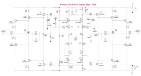
Gain: I kinda understood how to change gain through the 2 resistors (R16+R17)/R17. Clear so far. But what are reasonable steps—should I increase R16 (mo' gain) or decrease R17 (mo' gain)?
Ground: I was looking around for advices/hints at good grounding schemes...
and found most builds with no signs of grounding the amp other than through the PCBs and of course the transformer's earth...
OTOH, there was russellc I believe who went the firstwatt way with a star-ground-connection (again, ?) with a CL60 somewhere... is this the way to go?
thanks!
david
Thanks to all helping me out on my various questions.
2 more:
Gain: I kinda understood how to change gain through the 2 resistors (R16+R17)/R17. Clear so far. But what are reasonable steps—should I increase R16 (mo' gain) or decrease R17 (mo' gain)?
Ground: I was looking around for advices/hints at good grounding schemes...
and found most builds with no signs of grounding the amp other than through the PCBs and of course the transformer's earth...
OTOH, there was russellc I believe who went the firstwatt way with a star-ground-connection (again, ?) with a CL60 somewhere... is this the way to go?
thanks!
david
Grounds and their problems are funny things. In my builds, (might add I have NO electronics background other than what I have learned from DIY!) I followed 6L6 build guides.
I figured why not follow the tried and true method. Then, after it works and I have asked enough questions, I might bring on some change.
Check the 6L6 build guide on the BA3 as preamp. I used the same grounding scheme with that pre.
Follow what works if you are not an electronics whiz like many who share here.
When that works, you have a good foundation for any mods. Makes it a lot easier to troubleshoot if it doesn't work...
Russellc
Check the 6L6 build guide on the BA3 as preamp. I used the same grounding scheme with that pre.
Follow what works if you are not an electronics whiz (...)
Russellc
Thank you, Russellc
I following paths from way behind, as you see [emoji4]
Thank you, Russellc
I following paths from way behind, as you see [emoji4]
Nothing wrong with that, we have to begin somewhere!
Russellc
The line stage is 2nd harmonic both in simulation and in real life. I guess even if you matched everything it would still be 2nd harmonic?
Is it the FET input stage that is responsible for the 2nd harmonic character?
Is it the FET input stage that is responsible for the 2nd harmonic character?
I did my audio ground same as on the whammy and my build is dead silent. 🙂
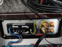
compact and very clean! (Is this a capacitor at the signal's ground?)
anyway, c'est très cool 🙂
Last edited:
Looking to build this linestage to drive the F4, how many volts can this output swing p-p?
I think I was getting close to 29.7VPP on +/- 18V supplies on the BA2018 (set for 10X or 20dB gain) with KSC2690/KSA1220 outputs on a scope (1Mohm input impedance).
Best,
Anand.
It does look like a cap but I thought the idea was to float the signal ground from chassis ground via a thermistor and/or bridge rectifier. Keep them isolated unless something goes electrically very wrong... Maybe that's only an amplifier thing? I'm interested to know the answer too.
compact and very clean! (Is this a capacitor at the signal's ground?)
anyway, c'est très cool 🙂
Thank you and yes it's a 0.47uf / 250v cap.
compact and very clean! (Is this a capacitor at the signal's ground?)
anyway, c'est très cool 🙂
It does look like a cap but I thought the idea was to float the signal ground from chassis ground via a thermistor and/or bridge rectifier. Keep them isolated unless something goes electrically very wrong... Maybe that's only an amplifier thing? I'm interested to know the answer too.
It was done on the whammy as recommended in the build guide so I did it on the Linestage too. Very effective. No hiss, buzz, hums or anything. Crank the volume right up with nothing playing and it's as silent as can be.
Since this has balanced inputs, is there any easy way to build it with balanced outputs? Without building two of them? I live in a very noisy environment and get terrible hum when using single-ended cables...
here it is, but make it on own risk
no reason it would not work flawlessly right off the bat, but it also could ask for some taming
edit:
you id mention balanced inputs, I did this with original schematic from post #1, where input is strictly SE
can't remember where iteration with Bal input is posted
Attachments
Last edited:
Thank you and yes it's a 0.47uf / 250v cap.
Do you have a part number or spec for that ? I tried entering the number on the Whammy cap into Digikey and Mouser and got 50 thousand choices.....


Last edited:
- Home
- Amplifiers
- Pass Labs
- Wayne's BA 2018 linestage