That is a decorative cover, EV did that too.
It didn't do much, and that's why they don't do it now.
It didn't do much, and that's why they don't do it now.
decorative cover ?
@ djk
I agree it's not the biggest heatsink on the planet, but it is one 😉 I can only repeat what i posted earlier,
At least they realised it was a factor in the grand scheme of things & tried to do something about it.
I guess bigger/longer fins would help !
@ djk
I agree it's not the biggest heatsink on the planet, but it is one 😉 I can only repeat what i posted earlier,
I asked Brian Mckenzie if it was just cosmetic, or did it really do much, and was told that it most definately made a difference.
At least they realised it was a factor in the grand scheme of things & tried to do something about it.
I guess bigger/longer fins would help !
It would also help if it tied into the top plate and pole piece, not the back plate.
It's cosmetic.
It's cosmetic.
Last edited:
Yes, that's true. The hottest place is definitely the center pole and top plate. The rear plate gets warm to the touch, but that's really not a big deal, and any heat sink attached to the back plate is pretty worthless. It's kind of on the right track, but not the right place to focus. The thing to do is to machine the pole piece to accept a cooling plug that can fit in a manner that maximizes surface area in order to improve the thermal interface.
The Kilomax approach is good, but I think the sink in front is too small. It's kind of limited by the fact that a larger plate would block the cone. You don't need a huge heat sink, but you do need more than that. I think the best thing to do is to exit the cooling plug out the back, where a larger heat sink can be attached. In the case of the 12Pi hornsub, the access plate conveniently serves as the heat sink, and it has plenty of mass and surface area, more than enough.
The Kilomax approach is good, but I think the sink in front is too small. It's kind of limited by the fact that a larger plate would block the cone. You don't need a huge heat sink, but you do need more than that. I think the best thing to do is to exit the cooling plug out the back, where a larger heat sink can be attached. In the case of the 12Pi hornsub, the access plate conveniently serves as the heat sink, and it has plenty of mass and surface area, more than enough.
The Kilomax approach is good, but I think the sink in front is too small. It's kind of limited by the fact that a larger plate would block the cone. You don't need a huge heat sink, but you do need more than that. I think the best thing to do is to exit the cooling plug out the back, where a larger heat sink can be attached. In the case of the 12Pi hornsub, the access plate conveniently serves as the heat sink, and it has plenty of mass and surface area, more than enough.
But the question on the kilomax is still....
1. is it patent infringing? My reading says yes.
2. what date was the kilomax introduced?
3. If it was non investigated prior art to the filing in 2006, what does that do to the current patent?
And as to the small sink of the kilomax -- it has air blowing on it... doesn't that negate some of the need for size?
We could discuss patent law, and I could tell you what the lawyers and examiners said about that prior art and others. But is that really interesting? I guess I kind of prefer the technical discussions.
I will say this, the Kilomax approach is not the same. Close, but not the same. I do think the Kilomax method is very good though. And yet, as I said, I think going out the back is better, because it doesn't interfere with the cone.
I will say this, the Kilomax approach is not the same. Close, but not the same. I do think the Kilomax method is very good though. And yet, as I said, I think going out the back is better, because it doesn't interfere with the cone.
4-5 years ago, I modified some Dayton aluminum cone 7" woofers by adding an aluminum phase plug to aluminum threaded rod that on the back side of the speaker was attached to a round heatsink designed for a PC. I never tested the power handling increase, but both the phase plug and the heat sink would kick off quite a bit of heat after prolonged abuse.
A litle bit of history on the system development:
I mentioned earlier that my first efforts focused on getting the heated vent air out of the rear chamber. I ducted them outside to an intercooler. My thoughts were that this would ensure that the cooling vent always had an ample supply of cool air, and also that any chuffing sound from the cooling vent would be muffled.
The first link (Loudspeaker Venting and Cooling Techniques) is interesting, I think, because it shows how I first assumed the same things many other people do. I started with the assumption that getting the magnet out into cool air would help. I also initially sought to use woofers with shorting rings. I have always prefered midwoofers and midranges with shorting rings. But after doing a lot of tests, building prototypes and evaluating them and measuring the results, I ultimately chose to use cooling plugs and push-pull drive, basically a complete reversal of my initial directions.
It is perhaps interesting to see the evolution of the design, why push-pull drive was chosen over shorting rings and why the cooling plug was chosen over the ducted intercooler approach. These are technologies that really work in a hornsub.
One thing that has remained sort of an aside is the chuffing sound from the vent. I was concerned about this initially, because my fear was that if it weren't muffed, it might be amplified by the horn. But the low-pass from the front chamber attenuates it. One of the benefits of a THD+N measurement is it will pick up non-harmonically related distortions, as the "N" part of the THD+N, the "noise".
It is clear from the 12Pi hornsub distortion measurements that the chuffing sound is inaudible. This may or may not be the case in other loudspeaker systems where the magnet is exposed.
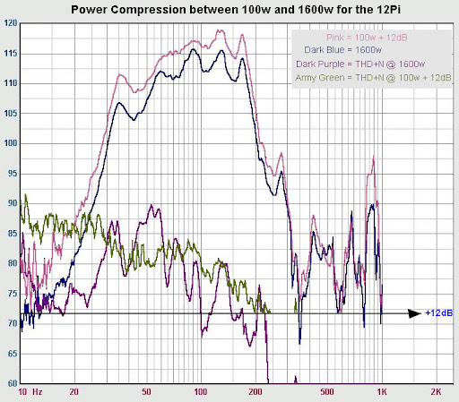
It is interesting look at power compression of the 12Pi.
What I did was lift the 100w SPL plot with 12dB (which is the equivalent of 16x power because 16x 100w = 1600w). The difference between the two SPL plots is the power compression frequency related. I kept the horizontal axis of the 100w measurements intact to show the accuracy of the 12dB lift of the 100w measurements.
What is remarkable is how the THD suppression by the Push-Pull system seems to do its work, even at 1600w and severe power compression.
Also can been seen that at 55Hz the power compression is low with 2dB where the excursion is max which is a very nice figure, indeed. However, the highest power compression as expected is down low with a figure of 4,9dB at 35Hz.
As TB46’s model in post # 133 tried to prove the problem is down low at 33Hz you can also see how well the power compression of about 5dB suppresses the extreme excursion as predicted. So Oliver, it means in reality the system seems to keep excursion under control below 50Hz. Therefore the 12Pi can be used safely to 30Hz as Wayne already claimed.
Wayne, I do agree you can use the 12Pi to 2Kw although the extra 200w per driver wont make a difference. However, it also proves the 13mm Xmax is never going to be reached which makes the total displacement much less than prediction suggests.
On the other hand, the Push-Pull and the cooling plug do indeed a tremendous job in their function. Keeping 5 to 6dB power compression under (thermal) control with exceptional low THD figures is a real achievement.
Last edited:
About displacement:
For the Eminence Lab12 that is [Sd x Xmax] = 506.7cm^2 x 1.3cm = 658.71cm^3. That means, in a dual setting they both will have a max displacement of 1317.42cm^3.
The total volume of the 12Pi is 929 litres.
The B&C 18SW115 mentioned in earlier posts has an displacement of 1,6 (Xvar) x 1210cm^2 = 1936cm^3.
Interesting is to compare two THAM’s loaded with 18Sounds 15LW1401 (100,5dB sensitivity for each cab) for instance, both would have a total volume together of 310 litres. This means 2 THAMS are only 30% of the volume of the 12Pi!
The18Sound 15LW1401 we can have a displacement for each driver of 0,9cm (Xmax) x 900cm^2 = 810cm^3. For two driver’s that is 1620cm^3. However, the 15LW1401 has an Xvar of >10mm, which means a displacement of >1800cm^3
In the graphs you can clearly see that the higher displacement and the lower power compression figures in the Tham's are paying off at max power ratings.
While the 12Pi has a reserve of about 400w, both Tham's have a reserve of 1000w.
Below 40Hz the Tham's are no competition for the 12Pi.
Interesting is to compare two THAM’s loaded with 18Sounds 15LW1401
Are you talking about the THAM mentioned in this thread?
If so, then I do not believe you can do much more than seat-of-the-pants comparisons. It doesn't appear to have matured, and is still being modeled. Is there other information out there on it?
To be honest, while I'm sure it's a fine speaker and it looks easy enough to build, I do not expect it to be anywhere near as efficient as the 12Pi hornsub. It's much smaller, which is cool and all, but small size limits its efficiency. It's more a tapped quarter-wave pipe than a horn.
Then there is the matter of scaling double-power as 3dB. As you know, that works pretty well at low power levels but not so much at high power levels. Yet in your charts, the 3000 watt chart shows about a 3dB increase over the 1500 watt chart. Seems a bit optimistic.
What would be best would be to actually measure the speaker at 3000 watts. I personally don't believe the THAM/15LW1401 would be a match for the 12Pi at 1600 watts, but only measurements would show for sure. Even going up to 3000 watts on the THAM would give a smidge more output, but I doubt it would equal the 12Pi (at 1600 watts) even given double the power.
I don't think even two of those THAM cabinets would be a match. Not enough mouth area.
You can't get around the matter of efficiency, even with increased excursion. There's just too much to overcome when efficiency is reduced. It's an exponential thing.
Those are just my educated guesses from looking at the design. Can't know for sure without a battery of tests.
Last edited:
Hi Wayne,
First of all, I did make a minor mistake as the two Tham’s count for a total of 390Litre.
The compression at 1000w each (2Kw total) is about 3,1dB with one big power compression dip of 4,2dB at 83Hz (which has to do with a correction panel that supposes to correct the 166Hz dip). That means at 83Hz there is no more gain. Since Tom didn’t have 1500w measurements I took his 3Kw measurements and lowered that 2,5dB to make the second plot, so you have a point there that the second plot is on the low side. It also is a fraction to much to the left. The intention was to show the difference in power compression levels vs output.
In the THAM thread you can find measurements from other users which you can check.
One extra note, he used two dynamic low-cut filters (filters that raise their points as more dB’s are added) to keep excursion under control and which is why the graphs become more bell type looking. These cabs are used in one of his private sets since and are driven by bridged Fp 2600’s, non of the drivers have failed yet. To give you a comparison, above 50Hz they keep up pretty well with our industry standard TSW-218 (in singles of course).
It looks like you don't believe TH's are capable doing so, which I can understand from your side, you didn't give any comment on the power compression data for your 12Pi, does that mean you agree on that part so far?
From what I see, the THAM should act more like a tapped quarter-wave pipe than a horn, since the taper is so slight. I would expect one would need three or four of these kinds of devices to match the output of one 12Pi hornsub. Again, it's a matter of efficiency, which is a matter of impedance transformation, which in turn, is a matter of area expansion in the flare profile.
I didn't see any measurements for the THAM, perhaps you could link to them? I would prefer an outdoor measurement that isn't modified by electrical filters. Best if done at a distance of ten meters, because if it's not made at least that far away, then the results might not be very accurate due to path length differences.
The woofer in a tapped horn/pipe, for example, is usually very near the mouth. But in a full-size horn, it is several meters back from the mouth. So if the measurement microphone is placed just two meters away from the face of the speakers under test, then it is two meters from the woofer in a tapped horn and more than twice that far for a full-size horn. That's a problem, with the inverse-square law making the two measurements somewhat incompatible. But if you move the measurement microphone out to ten meters, then the difference in the distances to the sources is less. There is still more distance to the woofer of the full size horn, but it isn't twice as far, only maybe 30% further (10 meters verses 13 meters). That's an acceptable difference, and makes path length error less significant.
Last edited:


Sorry if I sound like a broken record, but there's no way a pipe (tapped or otherwise) is going to have the same efficiency as a horn. There's no impedance matching mechanism without the flare.
There's no free lunch. If you want the efficiency, you must have the impedance transformation, and that requires some space for the area expansion.
Also, as I said, if you don't measure at a distance the measurements cannot be compared. In a true horn, the source is further away than it is in a tapped horn/pipe. The difference in source distance is significant, given the inverse-square law.
A few pages back, I posted a link to a Keele paper that describes the impedance matching and optimum mouth size. Here's another paper, written by Martin King, that also does a good job of explaining why the area expansion of the flare profile and large mouth size are important:
As an aside, as most of you are aware, Martin King has been building tapered quarter-wave pipes for quite some time, and did a lot of work to develop mathematical models for them. One of the most important things he did, in my opinion, was to show that response ripples from odd-multiples of quarter-wave resonance could be effectively mitigated by offsetting the source position in the line. His models help a designer find exactly where to place the driver in the line to smooth response down low. This is very much the same approach used in a tapped horn.
The thing is, whether or not a transmission line or horn is "tapped" - with driver offset - the overall efficiency is a function of the impedance matching, which is a function of the length, throat and mouth size. The tapped horn concept is not really intended to increase efficiency, it is intended to smooth ripples in response of a compromised basshorn. It is primarily effective in the frequency region where the frequency is between 1/4λ and 1/2λ, and it trades smoothness in this region for increased spikes at higher frequencies. The tapped horn approach does this by offsetting the source in the line, to smooth out the quarter-wave resonances. Efficiency is still largely a matter of size, whether or not the source is at the (traditional) apex or offset (tapped).
A basshorn is almost always compromised, meaning the mouth size isn't large enough. But if a horn is designed to be used in groups, it can be made so that it is uncompromised when a certain number are used together. In this case, efficiency is maximized and there is no response ripple or reduction of output in the lowest region, between 1/4λ and 1/2λ. This is the way the 12Pi hornsub is designed.
Optimization is required for this kind of efficiency. If you optimize a cabinet for extension and small size, you can't necessarily expect it to scale up when used in groups. You can't just take a severely truncated horn and put it in groups and expect this efficiency increase. If the flare rate is small, i.e. very little taper, then no amount of grouping will help. The area expansion is still not right. This is why transmission lines can't "become" horns when used in groups - there is no taper. It is a requirement that the mouth size be large enough and the expansion rate be right for efficiency to be high.
The statement “the difference in source distance is significant, given the inverse-square law” was one of those things I’d heard over the years, but had never seen any actual proof for or against.Sorry if I sound like a broken record, but there's no way a pipe (tapped or otherwise) is going to have the same efficiency as a horn. There's no impedance matching mechanism without the flare.
There's no free lunch. If you want the efficiency, you must have the impedance transformation, and that requires some space for the area expansion.
Also, as I said, if you don't measure at a distance the measurements cannot be compared. In a true horn, the source is further away than it is in a tapped horn/pipe. The difference in source distance is significant, given the inverse-square law.
Having both horn load and front loaded cabinets available, I decided to investigate how they compared at various distances, tested on Saturday May 15, 2010.
My tests were a bit hasty, but basically showed from 1 to 30 meters, both a horn load with about 60-65 inch path length and a front loaded cabinet both fall at the inverse square law.
Phil Lewandowski repeated the experiment in more detail under better conditions (mine were affected by building proximity and wind) with singles and pairs of bass reflex JBL SRX 718 and horn loaded JTR Growlers. The JBL SRX 718 and JTR Growlers radiating area is similar, though the FLH Growler path length is probably around 60-70 inch.
PSW Sound Reinforcement Forums: LAB: The Classic Live Audio Board => Directional Subwoofer Arrays
Message # 548171 my results
Message # 551418 Phil’s results
Phil’s results show virtually no difference in the SPL decline between the horn loaded and front loaded cabinets, and both conform almost exactly to the inverse square law as would be predicted from 1 to 30 meters from either cabinet’s front.
This proves that the apparent acoustic origin (source distance as you put it) of the horn cabinet is at the mouth, not the throat or speaker location.
I still would agree that test distances of 10 meters or more are best, especially if comparing multiple sub enclosures which have a large frontal area. but the facts say the acoustical origin is at the horn exit (mouth) not the throat.
In very near field conditions, say at the grill, a small exit producing the same SPL as a large exit (a .5 square meter front load or TH exit compared to a square meter horn exit) will read higher than the larger exit, but at distances of a meter or more the size difference and internal location of the driver is of no consequence.
As far as your other statement regarding impedance transformation, given the same size restrictions, TH can and do outperform FLH as far as efficiency and SPL output goes.
That said, in large arrays of large TH compared to large FLH the difference becomes less, and may tilt toward the FLH, as TH do not have the additional LF gain in multiples that mouth size compromised FLH do.
That is no doubt the reason DSL uses TH in the most of their line of subs, but is using FLH in some of their very large (even larger than the 12Pi) enclosures.
Art Welter
This proves that the apparent acoustic origin (source distance as you put it) of the horn cabinet is at the mouth, not the throat or speaker location.
No, the acoustic origin is the radiating diaphragm. The horn is an impedance matching device, which extends some distance from the source.
You can sort of think of "the box" as the source, but from a technical perspective, the diaphragm is the source.
When designing a crossover, you most certainly would not consider the source location to be the mouth, would you? If you aren't delaying the mains to match the subs, then performance would be, well, pretty bad.
If we were talking about diffraction, then we might consider an edge to be an apparent source. In high frequency horns, for example, the apparent source can shift from the diaphragm to a diffraction slot in the throat when measurement is made off-axis. But even when diffraction is present, the delay from path length is evident.
The on-axis source location most certainly is the radiating diaphragm, not the mouth.
Hi Wayne,
I would suggest, that for comparison purposes all enclosures should be treated as black boxes with a mouth. While the actual path length may well be very important for all kinds of analysis, when comparing loudspeakers they should probably be compared as black boxes, e.g.: volume/power in/power out/distortion. The end user doesn't really care if it's a horn or a squirrel cage operated siren. 🙂 Also, Danley has a good point when he recommends 10m as measurement distance.
Regards,
- Status
- Not open for further replies.
- Home
- Loudspeakers
- Subwoofers
- Wayne's 12Pi sub