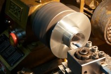
Can anyone comment on how the Fane 8m will go with a JMMLC200 with a 125mm opening?
I will use a 3lt (approx) rear chamber for the driver.
http://www.diyaudio.com/forums/multi-way/185681-my-le-cleach-horn-build-15.html
I will use a 3lt (approx) rear chamber for the driver.
http://www.diyaudio.com/forums/multi-way/185681-my-le-cleach-horn-build-15.html
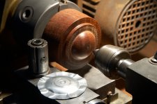
Spun aluminum domes.
Use less tool pressure & make more passes to arrive at the finished profile. As the profile develops, change to a larger live center pressure pad (reverse profile) to better distribute the torsional forces.
Use less tool pressure & make more passes to arrive at the finished profile. As the profile develops, change to a larger live center pressure pad (reverse profile) to better distribute the torsional forces.
Last edited:
Spun aluminum domes.
Use less tool pressure & make more passes to arrive at the finished profile. As the profile develops, change to a larger live center pressure pad (reverse profile) to better distribute the torsional forces.
Sounds like advice from a guy that has spun a little aluminum over the years!
Spun aluminum domes - first trial. Plate thickness is 0.1mm, corrugations and cracks appears quickly.
I expect results are very sensitive to alloy and temper - did you use one recommended for that process?
Ah 🙂
Now if you could find out what's a suitable type for deep drawing, or try annealing the can material.
Or try cutting the material from the bottom, as it's closer to the final shape.
Now if you could find out what's a suitable type for deep drawing, or try annealing the can material.
Or try cutting the material from the bottom, as it's closer to the final shape.
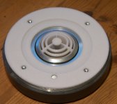
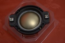
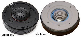
The NSD1095N is currently my favorite 1" compression driver. Are you modding the phase plug on it?
Jacek
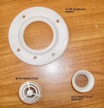
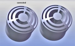
If thats is supposed to be a Fresnel phase plug then each open section should be of equal area. Somehow that just doesn't look right. Are you sure that eaach opening has equal area?
If thats is supposed to be a Fresnel phase plug then each open section should be of equal area. Somehow that just doesn't look right. Are you sure that eaach opening has equal area?
I did typo in the first ring from diaphragm side but all in all 3D print is limited on wall thickness and we must take it into account - this 3D print is rough. No problem with a new one and for example 0.5 inch.
Last edited:
Well you need to review the patent again, because the concept of equal areas for all of the channels is critical, just as the concept of a Fresnel pattern also have equal areas. If the ares of the channels are not equal in area and equal in length the the wavefront at the aperature will not be constant, i.e. "flat". This is the central point of the patent.
So if you have three channels then the area of each channel must be exactly 1 / (3 * compression ratio) of the total area of the diaphragm.
The "centroids" tell you the locations for the channels, centroids match centroids, but nothing about their widths. The widths are defined such that each channel has an equal area and covers corresponding Fresnel areas of the diaphragm.
Last edited:
gedlee;2757211So if you have three channels then the area of each channel must be exactly 1/3 of the total area of the diaphragm.[/QUOTE said:Divided by compression ratio.
So you have good eyes for details 🙂
Compression ratio is 1:3
Compression ratio is 1:3
Attachments
Last edited:
- Home
- Group Buys
- Waveguides and horns