And presumeably the reason why Scott Wurzer quit this forum 😀That's exactly why I'm not a member at ASR. 😆
That’s spelled, Wurcer.And presumeably the reason why Scott Wurzer quit this forum 😀
Just ensuring that you at least got his name correct, if not his motivations.😎You are welcome to keep my typos 😀
He is still posting at ASR.
No wonder he disabled his account here. Just look at this very thread. Off topic posts and thread hijacking are more a rule than exception.
Scott's last post on ASR was a year ago. He had other reasons for leaving here.
Last edited:

Okey, i understand your purist thinking and fully respect your point of wiew.Musicality created by musician and sound engineer in music production. In music reproduction, I want linearity because I respect to who made the recording so the sound is as accurate as possible. I do not want to change the recording to fit my taste.
But i think the ”totally unaltered, uncoloured perfection game” is fundamentally flawed in the following way:
Musicians and sound engineers says:
”HiFi measurement Accuracy- smackuracy, we really, really dont understand or care! Twist them knobs to eleven. Lets go for extreme dynamic compression and loudness wars.”
They simply want to sell ”records”, they want you to like the stuff they are putting out, they want you to think it sounds VERY GOOD. They want you to give them more of your money.
And if your extra special hifi equipment chain makes it sound even better than in their flawed and not sonically perfect sound studio: REALLY good in your ears : Even better!
Accuracy-Smackuracy. The absolutely perfect, totally un coloured sound studio simply does not exist on this planet.
🙂🤚
The accuracy is of course a ghost many are hunting, from some musician to some engineers down to some consumers. For them (us), accuracy is a thing impossible to get to 100%, but we try to get as close as possible. (An acoustic instrument or a voice never sounds exactly the same through any reproduction, but it can get quite close! And how about electronic instruments? Can these be accurate at all, resp. what is accurate for them?)
Then of course there’s those seeking sales, and listenability in average car-audio, mediocre soundboxes etc., but these usually are different worlds/records…
Just my 2c
Then of course there’s those seeking sales, and listenability in average car-audio, mediocre soundboxes etc., but these usually are different worlds/records…
Just my 2c
Someone made a good point. Would the musician even know what is accurate to the original recording? Our brains aren't really equipped to remember sound to that degree of accuracy. However, we definitely are wired to be entertained. Our rooms pretty much screw up any chance of making things faithful to the original recording.
So having read through all of this thread during some extremely boring lecture I have to say, I really want to build something close to this amp. I need to know what this sounds like 😀
Problem is, I don't have access to the tube used here and I would probably need to use different FETs(might have the right ones but I haven't looked). What other tubes would be close to the same sound? I don't need a high output level, I'd probably drop it down with some resistors to use headphones anyway 🙂
Problem is, I don't have access to the tube used here and I would probably need to use different FETs(might have the right ones but I haven't looked). What other tubes would be close to the same sound? I don't need a high output level, I'd probably drop it down with some resistors to use headphones anyway 🙂
Use whatever tube and Fet you can get, technical parameters are irrelevant, all you need is to BELIEVE .
I think you are not understanding why I'd want to build this. This seems like somewhat of one extreme, as far as you get towards "warm" and "colorful" sound or whatever tube people say and I want to test that out. I also want to build a really nice and linear tube amp too because that's also fun.Use whatever tube and Fet you can get, technical parameters are irrelevant, all you need is to BELIEVE .
If I wanted nice, clean and good sound I'd just grab a €3 D class or whatever from the lab and end up better off probably.
Tube amps are kind of like a chopper motorcycle, completely unreasonable, nonsensical and hysterical and that's it's only raison d'être
A full tube amp does enough "things" to sound that it´s noticeable, so it´s worth building.
So much so, it´s easily measurable too, can be picked by most listeners in a DBT, etc. , I have nothing against and in fact I like them, go figure.
There is enough of a difference that different flavours are available, then people can like one or another.
I don´t argue taste, to each his own.
Now a line stage is so flat and uncoloured (by definition and by design) that claiming it meets all the over the top exaggerated claims in the OP is nonsense.
Exact same nonsense as arguing about taste preferences between 2 glasses of distilled water.
Think about it.
A major issue in building Fabrizio’s solid-state ‘WOTS-Tre’ design is that the transistors are out of production. I have the following suggestions:So having read through all of this thread during some extremely boring lecture I have to say, I really want to build something close to this amp. I need to know what this sounds like 😀
Problem is, I don't have access to the tube used here and I would probably need to use different FETs(might have the right ones but I haven't looked). What other tubes would be close to the same sound? I don't need a high output level, I'd probably drop it down with some resistors to use headphones anyway 🙂
1) ‘Small Bear Electronics’ lists stock of 5,600 pieces of the BF244B JFETS for $0.50 ea.
https://smallbear-electronics.mybigcommerce.com/transistor-fet-bf244b/
2) To replace the N-MOS output follower transistor, the ZVN3310A looks like a good and available substitute.
Regarding the triode based ‘WOTS-LeGrande’, I don’t believe the exact tube is critical, although Fabrizio might well inform otherwise. Basically, it’s a medium-mu, dual-triode with a 6.3V heater. If you utilize something other than a 6H30, you will probably need to adjust the two biasing resistors, R3 and R11, and the heater supply if using something other than a 6.3V tube. Also keep in mind that a different than specified triode will likely produce a somewhat different than intended sound although it may still prove quite satisfactory, but I don’t know. I believe that the specified N-MOS output follower transistor is still commonly available.
Last edited:
Alright, I'm thinking of replacing the tube with a 12BY7(A) and the output MOSFET with an IRF610 because I have both of those around. The IRF610 seems fairly similar to the FQPF3N25 after a quick skimm of the datasheet. Do you think these are fair substitutions?A major issue in building Fabrizio’s solid-state ‘WOTS-Tre’ design is that the transistors are out of production. I have the following suggestions:
1) ‘Small Bear Electronics’ lists stock of 5,600 pieces of the BF244B JFETS for $0.50 ea.
https://smallbear-electronics.mybigcommerce.com/transistor-fet-bf244b/
2) To replace the N-MOS output follower transistor, the ZVN3310A looks like a good and available substitute.
Regarding the triode based ‘WOTS-LeGrande’, I don’t believe the exact tube is critical, although Fabrizio might well inform otherwise. Basically, it’s a medium-mu, dual-triode with a 6.3V heater. If you utilize something other than a 6H30, you will probably need to adjust the two biasing resistors, R3 and R11, and the heater supply if using something other than a 6.3V tube. Also keep in mind that a different than specified triode will likely produce a somewhat different than intended sound although it may still prove quite satisfactory, but I don’t know. I believe that the specified N-MOS output follower transistor is still commonly available.
My initial feeling is that those are probably okay as substitutes, but I have not performed any analysis to support that feeling. I would like to add, however, that if you want to be assured that you are experiencing the same sound character which Fabrizio describes in his opening post, you should accurately replicate his schematic, including utilizing the specified parts, even though you understandably wish to make use of parts already in your parts drawer. For much better guidance on your questions, I suggest that you PM the designer, marigno (Fabrizio). I think you'll find him to be a good natured and generous fellow.Alright, I'm thinking of replacing the tube with a 12BY7(A) and the output MOSFET with an IRF610 because I have both of those around. The IRF610 seems fairly similar to the FQPF3N25 after a quick skimm of the datasheet. Do you think these are fair substitutions?
Particularly for circuits with little or no feedback almost any component substitution and or maybe a layout change can potentially have some effect on sound. IIRC for a simple MOSFET buffer we tried a few different parts and FQPF3N25 was one of the better sounding choices. Also IIRC IRF510 had pretty strong bass but was not that great on the highs. Don't know about specifically about IRF610 though.
Spot on. I've played in bands and recorded music for 15 years and spent most of my time hanging with people making music and going to shows. "accuracy" and "sounds like live" as a topic NEVER EVER came up. Nobody cares about that.Musicians and sound engineers says:
”HiFi measurement Accuracy- smackuracy, we really, really dont understand or care! Twist them knobs to eleven. Lets go for extreme dynamic compression and loudness wars.”
I don't know how many live shows I have played. But I know how many sound engineers listened to me playing up close directly without going through the house p.a. in order to make an attempt to mimic that as close as possible: not a single one, not a single time. No one cares. It's a hifi ghost story, or chasing the white rabbit or whatever you want to call. There is no accuracy in any recording, there is no accuracy to any amplified live music and there are several accuracies in acoustic live music, depending on your distance/angle/whatever to the music and how loaded you are.
Description of "WOTS LeGrand E2 project" - A pre-amp. Not the usual boring follower post-amp.
The "WOTS LeGrand" was born in 2004, as the successor of the "Aki'llower", in turn, the successor of the "AkiLine1" project proposed by the well-known Italian shop AudioKit.
The "AkiLine1", in my opinion, lacked some edge and punch. I'm sure this was my fault, as I had biased the triode to draw 15mA or more, which was too much for the design. I thwarted the presence of the anodic inductor, bridling its operation. I did this according to my belief that the more current flowing through a gain loop, the better its musicality. I respected the maximum current allowed by the inductor with a large margin, which, however, was higher than what was established by the project.
I then tried to add a resistor in series to the anode load to have half the supply voltage on the anode, and I applied a source follower, needless to say, a high current (45mA) one. This was the decisive step: the music now flowed pleasant and detailed proposing a credible and enjoyable scene. Which I hadn't been able to achieve with the very expensive "Aikido", which also seemed like a noteworthy project. At the end of the article, there is a note on the very simple modification to make "Aikido" perform well.
Then I removed the inductor, polarized the triode better (still negative rail is present), and the "Aki'llower" was born, the progenitor of the "WOTS LeGrand". It has remained unchanged since 2003 and still plays in my laboratory.
So I started working on the new "WOTS LeGrand" project in 2004. I removed the grid negative by recalculating the triode polarization for the maximum possible gain without using a cathode capacitor, I took great care of the power supply, I designed a PCB and made it at home (never again), and then I put it together. The preamp has been playing in one of my HiFi systems ever since, to my great satisfaction.
In 2008 my dear friend Gianfranco, who as a musician had very good ears, told me that he particularly appreciated the sound of my "LeGrand", but that he wanted to avoid tubes altogether. I designed for him the "WOTS Tre", a jFET cascode followed by a source follower. We spent an entire afternoon fine-tuning its sound with different polarizations, and when we were done, we got the same sound as the "LeGrand".
Other enthusiasts have built the two "WOTS", and have compared them with other preamplifiers; listening tests have also been carried out in various audiophile clubs, and the two "WOTS" have always been appreciated, and preferred to other high-cost "noble" devices. I myself went to see a designer of Hi-End amplifiers in his shop because I was interested in an OTL tube power amp. At the end of the listening tests, I asked if I could use my "LeGrand", which I brought. Perhaps it was due to the "rule of the beetle" (I'm not going to explain it, google "regola dello scarrafone"), but I was sure that the already excellent sound was even better than before; a fact confirmed by my friend Flavio, who accompanied me, and who noticed the grimace of "admired disappointment" on the part of the designer because he too understood that the LeGrand was better than his.
My friend Stefano, with whom we have been dealing for a long time since the beginning of the adventure, has tried and tried again different configurations of the "WOTS LeGrand", even a low voltage one; he had a lot of fun with it, finally landing on the use of the 6922 with paralleled triodes, without a pull-up resistor.
The "WOTS LeGrand", in its original version with the 6H30, listened to during various sessions, in Stefano's listening room in Rottofreno (PC - Italy), gave us goosebumps due to the warm mellowness and the ethereal transparency of its sound. Someone judged it a piano preamp for the precision of reproduction of this noble instrument; others marveled that for the first time they experienced almost the same feeling as during a live event. I myself stood there with a shiver running down my spine. We had 4 preamps to test in a chain that was not terribly expensive, but pretentious just enough. The WOTS LeGrand was, once again, the undisputed winner for expressed musicality, indeed very characteristic but completely devoid of color.
The simplicity of the scheme makes it clear that the only thing to calculate is the polarization of the tube, trying to keep the distortion low and monotonically decreasing, as befits an excellent single-ended. Since there is no loop feedback, and since there are few components, these must be high quality.
Some time ago I had the idea of assembling a second "WOTS LeGrand", revisiting the project to improve and update it. I added the suffix "E2" to his name, meaning "here's another one, the second one", which, in Rome, is precisely said "eddue".
Reading Boske (Tube CAD Journal) I convinced myself that the filament power supply should not be shared between the two channels, each channel must have its own filament power supply. It follows that I cannot use a single double triode valve for a stereophonic realization. So I decided to opt for a dual mono implementation, which presents the ground as the only common element between the two channels. The circuit is now a little more complex than the original, because:
Actually, I was tempted to use the PS21 proposed by Tube CAD Journal, but since it uses feedback to ensure rock-solid voltage stabilization, and since I am averse to any form of loop feedback, I revisited the old and "wise" Virtual Battery.
The original "LeGrand" uses a 6H30, which gain is just sufficient for a line preamp, provided the cathode resistor is low enough. With a low resistor on the cathode, in order to polarize correctly the triode, a pull-up resistor is needed. In the PCB design, I kept the pull-up resistor; if a 6922 is used, this is not needed, since the 6922 has a higher gain.
The components are up to date with what the market currently offers and what I have managed to fit into the PCBs. Basically, nothing has changed compared to the original 2004 project, only some new refinements allowed by the new components I came to know, and the dual-mono circuitry.
I really don't like to design PCBs, it is a kind of job very boring for me (just like the followers are for some diyaudio forumers), and I do it without the needed attention and concentration. But this time I had to. What I enjoyed, this turn was finding a solution to obtain a symmetrical design with only one board, so I had to pay for the making of only 1 PCB, good for both channels. So I designed two PCBs, one for the audio section, and the other for the power supply section, double-sided with through holes, with the reversibility criterion I had in mind.
Building the "WOTS LeGrand E2" does not present particular difficulties or critical issues, it is a project for all enthusiasts who:
The mechanical part and PCBs are designed to fit the 2U (minimum) high, 350mm deep HiFi2000 Slim Line cabinet with a mounting base and fully vented covers. The PCBs are not well suited to other cabinets.
The following mechanical details must be made:
Fasteners to buy:
After listening to different solutions with 6H30 and 6922, my final choice is the 6922 polarized at 7.5mA for each triode, with no pull-up resistor. In this way it seems to me to be back in 2004, testing the "LeGrand" at Stefano's. The same sound, perhaps now a little better with the 6922, which was also Stefano's choice in his last "LeGrand". The quiescent point is 1.2V on cathode, 75V approx on the anode, 0.56W each triode. The schematic shows this configuration.
The PCB offers two possibilities in order to apply the load to the source follower: a CCS or a resistor. I definitely prefer the resistor, which gives more body, detail, and focus to the sound. Perhaps a purist would choose the CCS, which gives a sound very close to Aikido's (once improved).
While writing this note I have some cross-over music flowing in the room at a very high volume, but it doesn't bother me, meaning that the "LeGrand" doesn't generate any listening fatigue.
Be aware that some fake DN2540N5/DN2535N5 are around the market. My first attempt to build the 'LeGrand E2" failed because of them, I understood that when I received the DN2535N5 bought from an official retailer. The reason you see a resistor in place of the DN2535N5 in the power supply board is that I ran out of them, and have to order some more good ones.
Should you decide to try this adventure, I can send you the Gerber files of the PCBs, just send me a note in PM.
"Aikido": make it sound.
The circuit proposed by Broske has a clearly captivating topology, linearity, and good sound that can be read from the schematic. It is a single-ended loaded by a CCS, (half mu) followed by a cathode follower, also loaded by a CCS. A scheme that promises very well.
Promises, but doesn't keep! I don't like the sound produced by Aikido. And all the people I know who have heard it have the same opinion as me.
What spoils the sound of this very elegant scheme? Found! It is the accessory circuit (1 capacitor, 2 resistors - 1C2R) implemented to reduce the noise present on the power line. Useless, because if I decide to do "Aikido", I already know that I will have to face a considerable expense, and I certainly won't think of saving on the power supply. If the power supply is well-designed, it is safe to assume that there will be no noise on the power line. Therefore the accessory circuit aimed at reducing the disturbances on the power supply line becomes useless. But it is not harmless, because there are certainly residues of the audio signal on the power line which, by their nature and magnitude, would not be harmful. But if I take these residues and put them in the grid of the low right triode, they are amplified and become part of the signal that is sent to the main amplifier connected to the preamplifier.
I tried removing just the capacitor carrying the signal from the power line, biased the grid with a 470-Ohm resistor to the ground, and listened. The difference, for the better, is no small matter. Finally "Aikido" sounds! I immediately compared my idea on the DIYAudio forum and got the confirmation: I'm not the first to propose this modification! It had already been tested successfully.
Operation of "Aikido" as a headphone amplifier: in this case, a low-value resistor must be inserted on the power supply line. On the hot side of the resistor, a signal is generated which reaches the lower right grid, through the accessory circuit 1C2R, activating the push-pull operating mode, from which derives a lower output impedance. This is the true utility of the 1C2R accessory circuit. You could also activate the "Gomez" topology in a very easy way, by connecting the lower right grid together with the lower left one, and obtaining the push-pull operating mode, but you better read what Broske says about this topic. I tried the "Gomez" way up to read 110Vpp on 1KOhm load and the sinusoid was perfect.
The "WOTS LeGrand" was born in 2004, as the successor of the "Aki'llower", in turn, the successor of the "AkiLine1" project proposed by the well-known Italian shop AudioKit.
The "AkiLine1", in my opinion, lacked some edge and punch. I'm sure this was my fault, as I had biased the triode to draw 15mA or more, which was too much for the design. I thwarted the presence of the anodic inductor, bridling its operation. I did this according to my belief that the more current flowing through a gain loop, the better its musicality. I respected the maximum current allowed by the inductor with a large margin, which, however, was higher than what was established by the project.
I then tried to add a resistor in series to the anode load to have half the supply voltage on the anode, and I applied a source follower, needless to say, a high current (45mA) one. This was the decisive step: the music now flowed pleasant and detailed proposing a credible and enjoyable scene. Which I hadn't been able to achieve with the very expensive "Aikido", which also seemed like a noteworthy project. At the end of the article, there is a note on the very simple modification to make "Aikido" perform well.
Then I removed the inductor, polarized the triode better (still negative rail is present), and the "Aki'llower" was born, the progenitor of the "WOTS LeGrand". It has remained unchanged since 2003 and still plays in my laboratory.
So I started working on the new "WOTS LeGrand" project in 2004. I removed the grid negative by recalculating the triode polarization for the maximum possible gain without using a cathode capacitor, I took great care of the power supply, I designed a PCB and made it at home (never again), and then I put it together. The preamp has been playing in one of my HiFi systems ever since, to my great satisfaction.
In 2008 my dear friend Gianfranco, who as a musician had very good ears, told me that he particularly appreciated the sound of my "LeGrand", but that he wanted to avoid tubes altogether. I designed for him the "WOTS Tre", a jFET cascode followed by a source follower. We spent an entire afternoon fine-tuning its sound with different polarizations, and when we were done, we got the same sound as the "LeGrand".
Other enthusiasts have built the two "WOTS", and have compared them with other preamplifiers; listening tests have also been carried out in various audiophile clubs, and the two "WOTS" have always been appreciated, and preferred to other high-cost "noble" devices. I myself went to see a designer of Hi-End amplifiers in his shop because I was interested in an OTL tube power amp. At the end of the listening tests, I asked if I could use my "LeGrand", which I brought. Perhaps it was due to the "rule of the beetle" (I'm not going to explain it, google "regola dello scarrafone"), but I was sure that the already excellent sound was even better than before; a fact confirmed by my friend Flavio, who accompanied me, and who noticed the grimace of "admired disappointment" on the part of the designer because he too understood that the LeGrand was better than his.
My friend Stefano, with whom we have been dealing for a long time since the beginning of the adventure, has tried and tried again different configurations of the "WOTS LeGrand", even a low voltage one; he had a lot of fun with it, finally landing on the use of the 6922 with paralleled triodes, without a pull-up resistor.
The "WOTS LeGrand", in its original version with the 6H30, listened to during various sessions, in Stefano's listening room in Rottofreno (PC - Italy), gave us goosebumps due to the warm mellowness and the ethereal transparency of its sound. Someone judged it a piano preamp for the precision of reproduction of this noble instrument; others marveled that for the first time they experienced almost the same feeling as during a live event. I myself stood there with a shiver running down my spine. We had 4 preamps to test in a chain that was not terribly expensive, but pretentious just enough. The WOTS LeGrand was, once again, the undisputed winner for expressed musicality, indeed very characteristic but completely devoid of color.
The simplicity of the scheme makes it clear that the only thing to calculate is the polarization of the tube, trying to keep the distortion low and monotonically decreasing, as befits an excellent single-ended. Since there is no loop feedback, and since there are few components, these must be high quality.
Some time ago I had the idea of assembling a second "WOTS LeGrand", revisiting the project to improve and update it. I added the suffix "E2" to his name, meaning "here's another one, the second one", which, in Rome, is precisely said "eddue".
Reading Boske (Tube CAD Journal) I convinced myself that the filament power supply should not be shared between the two channels, each channel must have its own filament power supply. It follows that I cannot use a single double triode valve for a stereophonic realization. So I decided to opt for a dual mono implementation, which presents the ground as the only common element between the two channels. The circuit is now a little more complex than the original, because:
- both triodes of the valve are used paralleled, with the foresight of having inserted a degeneration on each cathode;
- there is a resistor for each grid;
- I inserted a divider to polarize the gate of the mosfet at half voltage, useful only during any experiments, in the final version it should be omitted;
- it is possible to choose, by moving a jumper, whether to use a CCS or a resistor as a load to the source follower, according to and respecting the preference of my friend Flavio who has a very sharp ear, and who recently asked me for this modification;
- the Virtual Battery type power supply is simplified and improved thanks to the adoption of silicon carbide rectifier diodes and for having used a depletion mosfet as CCS to power the zener.
Actually, I was tempted to use the PS21 proposed by Tube CAD Journal, but since it uses feedback to ensure rock-solid voltage stabilization, and since I am averse to any form of loop feedback, I revisited the old and "wise" Virtual Battery.
The original "LeGrand" uses a 6H30, which gain is just sufficient for a line preamp, provided the cathode resistor is low enough. With a low resistor on the cathode, in order to polarize correctly the triode, a pull-up resistor is needed. In the PCB design, I kept the pull-up resistor; if a 6922 is used, this is not needed, since the 6922 has a higher gain.
The components are up to date with what the market currently offers and what I have managed to fit into the PCBs. Basically, nothing has changed compared to the original 2004 project, only some new refinements allowed by the new components I came to know, and the dual-mono circuitry.
I really don't like to design PCBs, it is a kind of job very boring for me (just like the followers are for some diyaudio forumers), and I do it without the needed attention and concentration. But this time I had to. What I enjoyed, this turn was finding a solution to obtain a symmetrical design with only one board, so I had to pay for the making of only 1 PCB, good for both channels. So I designed two PCBs, one for the audio section, and the other for the power supply section, double-sided with through holes, with the reversibility criterion I had in mind.
Building the "WOTS LeGrand E2" does not present particular difficulties or critical issues, it is a project for all enthusiasts who:
- are familiar with voltages that can be dangerous to one's health;
- know which path must follow the mass connections;
- keep in mind, during the tests, that any metal piece connected only mechanically, to some component, must be referred to the mass, to avoid auto-oscillations;
- own a minimum of mechanical equipment including a drill (preferably a pillar drill), well-sharpened drill bits, some hole saws for making the holes for the valves and fans, files, a fretsaw, a ruler, and a digital caliper;
- has already successfully built an electronic device of medium difficulty;
- has the patience to proceed without the rush to listen to the first note.
The mechanical part and PCBs are designed to fit the 2U (minimum) high, 350mm deep HiFi2000 Slim Line cabinet with a mounting base and fully vented covers. The PCBs are not well suited to other cabinets.
The following mechanical details must be made:
- support for the potentiometer, input selector, and valves made out of a 2-inch L aluminum angle bar, 1/8 inch thick (it is possible to use a thinner bar, such as 1/16 inch), 270mm long;
- fittings for the semiconductors towards the sides of the container, made with a 2-inch flat aluminum bar, 1/8 inch thick (no less, due to the flared holes to be made to support the semiconductors), 280mm long;
- raised fixing surface for the toroidal transformer, made with a disk taken from a faulty hard disk (or with any piece of an aluminum bar), screws, and female/female brass turrets abutted on the base by means of countersunk screws;
- control shafts for the volume potentiometer and for the input selector, made with 6.3mm brass rod and female/female fittings, possibly operating in anti-friction bushings forced into the front panel.
Fasteners to buy:
- M3 10mm brass turret male/female qty 10;
- M3 20mm brass turret female/female qty 50;
- M3 8mm screws, possibly with hex head qty 100;
- M3 1mm screws with countersunk head;
- M3 various lenght screws with flat countersunk head;
- M3 various lenght screws with pan head;
- M3 nuts, washers, and lock washers.
After listening to different solutions with 6H30 and 6922, my final choice is the 6922 polarized at 7.5mA for each triode, with no pull-up resistor. In this way it seems to me to be back in 2004, testing the "LeGrand" at Stefano's. The same sound, perhaps now a little better with the 6922, which was also Stefano's choice in his last "LeGrand". The quiescent point is 1.2V on cathode, 75V approx on the anode, 0.56W each triode. The schematic shows this configuration.
The PCB offers two possibilities in order to apply the load to the source follower: a CCS or a resistor. I definitely prefer the resistor, which gives more body, detail, and focus to the sound. Perhaps a purist would choose the CCS, which gives a sound very close to Aikido's (once improved).
While writing this note I have some cross-over music flowing in the room at a very high volume, but it doesn't bother me, meaning that the "LeGrand" doesn't generate any listening fatigue.
Be aware that some fake DN2540N5/DN2535N5 are around the market. My first attempt to build the 'LeGrand E2" failed because of them, I understood that when I received the DN2535N5 bought from an official retailer. The reason you see a resistor in place of the DN2535N5 in the power supply board is that I ran out of them, and have to order some more good ones.
Should you decide to try this adventure, I can send you the Gerber files of the PCBs, just send me a note in PM.
"Aikido": make it sound.
The circuit proposed by Broske has a clearly captivating topology, linearity, and good sound that can be read from the schematic. It is a single-ended loaded by a CCS, (half mu) followed by a cathode follower, also loaded by a CCS. A scheme that promises very well.
Promises, but doesn't keep! I don't like the sound produced by Aikido. And all the people I know who have heard it have the same opinion as me.
What spoils the sound of this very elegant scheme? Found! It is the accessory circuit (1 capacitor, 2 resistors - 1C2R) implemented to reduce the noise present on the power line. Useless, because if I decide to do "Aikido", I already know that I will have to face a considerable expense, and I certainly won't think of saving on the power supply. If the power supply is well-designed, it is safe to assume that there will be no noise on the power line. Therefore the accessory circuit aimed at reducing the disturbances on the power supply line becomes useless. But it is not harmless, because there are certainly residues of the audio signal on the power line which, by their nature and magnitude, would not be harmful. But if I take these residues and put them in the grid of the low right triode, they are amplified and become part of the signal that is sent to the main amplifier connected to the preamplifier.
I tried removing just the capacitor carrying the signal from the power line, biased the grid with a 470-Ohm resistor to the ground, and listened. The difference, for the better, is no small matter. Finally "Aikido" sounds! I immediately compared my idea on the DIYAudio forum and got the confirmation: I'm not the first to propose this modification! It had already been tested successfully.
Operation of "Aikido" as a headphone amplifier: in this case, a low-value resistor must be inserted on the power supply line. On the hot side of the resistor, a signal is generated which reaches the lower right grid, through the accessory circuit 1C2R, activating the push-pull operating mode, from which derives a lower output impedance. This is the true utility of the 1C2R accessory circuit. You could also activate the "Gomez" topology in a very easy way, by connecting the lower right grid together with the lower left one, and obtaining the push-pull operating mode, but you better read what Broske says about this topic. I tried the "Gomez" way up to read 110Vpp on 1KOhm load and the sinusoid was perfect.
Attachments
-
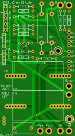 WOTS LeGrand E2 Audio PCB left side.JPG229.9 KB · Views: 310
 -
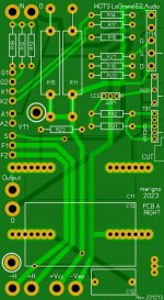 WOTS LeGrand E2 Audio PCB right side.JPG231 KB · Views: 256
 -
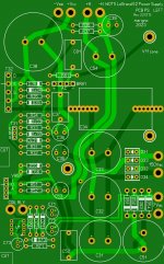 WOTS LeGrand E2 Power Supply PCB left side.JPG426.5 KB · Views: 250
 -
 WOTS LeGrand E2 Power Supply PCB right side.JPG427.5 KB · Views: 391
 -
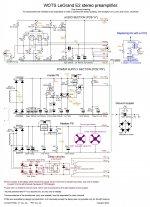 WOTS LeGrand E2 Schematic.jpg407.1 KB · Views: 444
 -
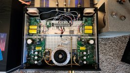 WOTS LeGrand E2.jpg576.2 KB · Views: 427

- Home
- Source & Line
- Analog Line Level
- Warmth Of The Sound - WOTS