Because he actually never built the amp.Why would you need to do that?
Not even finished designing it yet.
^^^^ that.Iʻm pretty sure that, in that case, the time constant is figured out using the standard RC equation.
True when the main goal is Engineering.I thought that the purpose of engineering was to find the simplest and most elegant solution?
My solutions would DEFINITELY involve SS which has been pre-rejected so, why bother?rather than post their voltage indicator solutions
LOVED the Dekatron.How about a dekatron tube as a spinning indicator
Oozing Steampunk goodness anc an object of beauty by itself, besides Electronic applications.
ALL my digital sources take longer to start up than the tube amplifiers to warm up. Switching to digital has actually been a regression on this aspect. It is hard to believe that anyone could be confused by a 15 sec delay at turn on. Anyway, on one of my amplifiers I fitted a EAM86/6GX8 level meter indicator. It does not require a solid state diode to operate (unlike more popular tube indicators) and it gives a nice visual reference of the amplifier state. I also tried the neon bulb solution on another amplifier (with tube rectifier). Being a neon tube, the bulb does light up suddently when the supply voltage exceeds the striking value, it does not have a gradual increase in brightness.
No SS? No problem. Just use tubes to build a 555 timer and use that for the indicator 😀
Should Have Used A Vacuum Tube 555 | Hackaday
Should Have Used A Vacuum Tube 555 | Hackaday
Realistically, this will work for you but the relay is out of stock right now @ LCSC. For a longer delay, use a tube that warms up slower, or starve the heater.
Attachments
Last edited:
So you're building a mono portable record player using a scrapped turntable. And you anticipate that this is likely to be snapped up on eBay by a tube newbie who is accustomed to instant gratification?Yes, I in the amp I am in the process of designing now, a simple single-ended mono phonograph amplifier intended to be paired with an old Garrard record changer that came out of an old Harman Kardon solid-state tabletop FM receiver that I junked
If the buyer is confused and complains about having to wait 20 sec for the amp to warm up, what will his reaction be when the turntable stops after playing only half the record?
How about using a time delayed input relay, that activates 5 seconds after the output cathodes are warmed up.
Add a 1kHz oscillator that goes through the relay contacts until the relay is activated.
After the relay is activated, the relay contacts apply the music signal source.
(The annoying 1kHz tone for 5 seconds will tell the listener that the amplifier is now warm,
even if the signal sources are not yet putting out music signals).
Sorry, I needed to do a little "Tongue in Cheek" for this 46 post thread.
....neon bulb and resistor connected at the third resistor/capacitor filter. The idea being that there is some time before the final RC section charges up, and when it does, it conducts enough voltage to start the neon. Thus, when the neon bulb indicator lights up, the amp is also ready to start playing music.....
How much delay does the RC network add?
Counting on thumbs, I got "not a lot". So I asked the mechanical idiot to plot it. Seems to be around a half a second?
That's on top of the rectifier warm-up. The 5AR4 is heater-cathode and will take some time. But warm-up time is not specified, and there are other tube type which will fit in the same socket.
But you have one. Is it really playing at the moment that neon lights?
Attachments
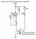
Yes, I in the amp I am in the process of designing now, a simple single-ended mono phonograph amplifier intended to be paired with an old Garrard record changer that came out of an old Harman Kardon solid-state tabletop FM receiver that I junked, I intend to use a 6CA4 rectifier tube (indirectly heated, separate filament and cathode pins on the socket). I think I have an idea of what it would potentially look like, adapted from the earlier Scott 200 schematic.
You will note that I am still using a relay to control the neon indicator, so that the bulb has sudden illumination action rather than a gradual increase in brightness.
Interesting, your use of the relay. As a practical matter, it may not be necessary. The "snap-on" of the neon bulb on my Scott happens in about 1.5 second at the most. In any event, I would put a small film capacitor .01 uf 600V) in line with a 100K resistor across the contacts, to quench any "arc" across the contacts, and to "speed up" the snap-on of the relay.
So you're building a mono portable record player using a scrapped turntable. And you anticipate that this is likely to be snapped up on eBay by a tube newbie who is accustomed to instant gratification?
If the buyer is confused and complains about having to wait 20 sec for the amp to warm up, what will his reaction be when the turntable stops after playing only half the record?
Okay, okay, I'll admit that I got a little carried away with my "hypothetical situation". I've been known to over-exaggerate things.
My solutions would DEFINITELY involve SS which has been pre-rejected so, why bother?
Woah, woah, woah, wait a minute...I never said I was completely against mixing solid state and tubes within the same unit! It's just that I wanted something that was considered an "all tube" unit. Hence I avoided fixed/grid bias (not even applicable since it's a single-ended unit) and preferred tube rectification. If there wasn't any other solution on earth, however, I would in fact consider a "hybrid" mix of tubes and SS...
I hope this clears everything up.
Last edited:
Woah, woah, woah, wait a minute...I never said I was completely against mixing solid state and tubes within the same unit! It's just that I wanted something that was considered an "all tube" unit. Hence I avoided fixed/grid bias (not even applicable since it's a single-ended unit) and preferred tube rectification. If there wasn't any other solution on earth, however, I would in fact consider a "hybrid" mix of tubes and SS...
I hope this clears everything up.
Ah! Then you could even do a 4 channel comparator that would "count down" as the voltage rose until all 4 lamps are off.


Isn't this thread a case of a solution looking for a problem, rather than stating the problem and looking at the most pragmatic solution?
Problem:
The customer wants a visual indicator that informs the customer the amplifier is ready to play music.
Solution:
Then put a delay on the B+, and extinguish a light when the B+ is turned on. That is simple, reliable and predictable.
In any other case the amplifier will be making a slowly ramping up distorted sound as it finally warms up. How is that intermediate state catered for?
This is way overkill. My Scott 200 integrated tube amp has an indicator that uses a neon bulb and resistor connected at the third resistor/capacitor filter.
For an amp today, I would use two indicators: an AC power on indicator, and the neon indicator to show B+ at the final RC stage.
Heathkit did the same thing as the pilot light. A neon bulb and a 470K resister hooked to the B+ When it's on the B+ is up and ready
You could make the light flash when warming up then go solid when ready? The class CD player next to me has states of power button:
red - standby
green blinking - warming up
green solid - ready
Seems not that difficult to make voltage divider to hit 1V when the B+ is ready. Use a NE555 for the blink. Even possible with optoisolating allowing the power button push and the state for the LEDs to be isolated.
Personally like a the main power on the back and a low voltage DC button on the front.
Heathkit did the same thing as the pilot light. A neon bulb and a 470K resister hooked to the B+ When it's on the B+ is up and ready
Yes, my Scott 200 only has the neon bulb as the pilot light. While it is acceptable, I do think from a safety standpoint it would have been good to have the AC pilot light.
NOTE: many tube equipment designs use a #47 6.3V incandescent bulb on the filament secondary winding as the pilot light. I do not like that design for two reasons: (i) it does not provide an absolute indication as to whether AC has been applied to the power supply; and (ii) the 6.3 v lamp is an additional load on the transformer, and many transformers are operating at or near their design limit (with greater heat generation on the windings.
For a new DIY build, I recommend using both an AC pilot light (wired in the AC switch circuit) so there is an absolute indication of AC being applied to the power supply(ies), and a B+ indicator using the neon bulb and resistor to show that B+ supply is active and the equipment is in a ready-to-operate state.
Some may also want a third indicator, if they also use an output delay relay to isolate the output so that no turn-on/turn-off thumps are passed on to the amplifier. The mute circuit PCB provided by Pete Millet has an option for such an indicator light. My old PS Audio IVH solid state preamp also had a circuit that blinked an LED during the time period while the preamp output was muted, and then went solid red on when the mute was defeated.
As a general matter, adding more indicators (annunciators) provides more information, but is one more thing to go wrong. It also adds cost. IMO, only the builder/user can determine what is best for the personal application.
Take an amplifier that has warm filaments/cathodes, and suddenly switch on B+.
Bang! Fzzz! do your ears and mind like those sounds in your loudspeaker?
Just the sound alone will announce that the amplifier is ready, even if your ears and speakers are not.
2 Steps Forward, and One Step back.
Just my opinions.
Depending on the exact design of your amplifier,
Your "Ready Sounds" May Vary.
Last edited:
Take an amplifier that has warm filaments/cathodes, and suddenly switch on B+.
Bang! Fzzz! do your ears and mind like those sounds in your loudspeaker?
Just the sound alone will announce that the amplifier is ready, even if your ears and speakers are not.
2 Steps Forward, and One Step back.
Just my opinions.
Depending on the exact design of your amplifier,
Your "Ready Sounds" May Vary.
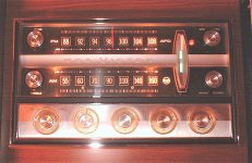
Ya know, my old 1963 RCA Victor console doesn't have anything being discussed here.
Ya pull the loudness knob out to turn it on.....
in a few seconds the tuning indicator glows, the neon stereo indicator lights up, and a few more seconds........ ya hear music!
It never needed any "delays" or dumb unneeded lights.
Attachments
- Home
- Amplifiers
- Tubes / Valves
- Warm Up Indicator Circuit