Hi. I am building a tube amp and I want to incorporate a warm-up indicator light as shown in my schematic. It acts as a visual indicator that the amp is warmed up and operating and is mainly intended to avoid confusion from newbies to the world of tube amps who, being accustomed to the instant start-up associated with solid-state amplifiers and electronics, may be potentially mislead into thinking the amplifier is defective when it actually isn't just because it makes them wait up to 15 seconds after turning it on before it lets them hear anything!
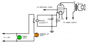
My circuit takes advantage of the rise in output tube cathode bias voltage to trigger a relay (with a DC operated coil) that has its armature wired in series with a #47 light bulb (this is in addition to the "normal" power pilot light). As the tube or tubes warm up, the voltage rises past the minimum "pick up" voltage required to trip the relay and, just like the pre-heating light on an oven, this causes the warm-up indicator light to go out, indicating to the observer that the amp is in fact warmed up.
Actually, I cannot take all the credit for this design. This actually was partially inspired by the "quick start" function on old Wurlitzer jukebox amplifiers. This involves a cathode-voltage controlled relay, but instead of using it to operate a light, it is used to temporarily increase voltage to the tube filaments when the cathodes are "cold", and switch to the normal 6.3 Volts when the tubes have warmed up.
I've done some preliminary tests in LTSpice that give some guidance for the design.
1. In a zero-signal state, the cathode bias voltage must be above the pick-up voltage of the relay. Otherwise, the relay will not trip and the warm-up light will stay on after the tubes have warmed up.
2. In a maximum-signal state, the tube should not be driven to the point where the cathode voltage exceeds the maximum rated voltage of the relay coil. Otherwise, the relay coil may be damaged or burned out.
3. Since the relay coil is in parallel with the usual bias resistor (Rk), this reduces the net resistance the cathode "sees" (Rnet=1/Rk+1/Rcoil). Therefore, cathode resistor Rk must be made significantly larger in resistance (ideally more than twice as large) in order to properly bias the tube or tubes than if the relay were not present.
However, in my LTSpice simulations, I want to take into account the effect of the inductance of the relay coil on the rest of the circuit. Unfortunately, the coil inductance is usually nonexistent on most relay data sheets. Could you guys help me out here?
Any other improvements you guys recommend?
Attachments
Maybe a comparator (powered by the filament winding) that toggles between
a red and a green led when the cathode voltage rises enough.
a red and a green led when the cathode voltage rises enough.
Last edited:
That is a nice idea. But I wanted to keep this an all-tube design if it's at all possible. There are still a lot of tube enthusiasts out there that cringe at the sight of a single semiconductor (except maybe aiodes or bridge nrectifiers in the power supply) in a tube unit.
Hence I went with #47 bulbs instead of LED's, and electromechanical relays instead of SSR's.
Hence I went with #47 bulbs instead of LED's, and electromechanical relays instead of SSR's.
This is way overkill. My Scott 200 integrated tube amp has an indicator that uses a neon bulb and resistor connected at the third resistor/capacitor filter. The idea being that there is some time before the final RC section charges up, and when it does, it conducts enough voltage to start the neon. Thus, when the neon bulb indicator lights up, the amp is also ready to start playing music.
For an amp today, I would use two indicators: an AC power on indicator, and the neon indicator to show B+ at the final RC stage.
For an amp today, I would use two indicators: an AC power on indicator, and the neon indicator to show B+ at the final RC stage.
If you must use the voltage change across the Rk as the trigger... Then I would maybe think of using a very high impedance sensing shunt rather than shunting the relay coil directly. Maybe use a computer tube as a switch with its grid sensing the rise. The sensing shunt would be in the megohms and not affect the cathode circuit at all. Boolean logic with tubes IOW to keep the purists happy.
Last edited:
I use something similar but a MOSFET instead of a relay. That way my cathode circuit has a more predictable impedance. Relays may vary and if using different relay the impedance may be very off design value. But your idea is not bad if you want to use low impedance on the cathode. Can the relay coil somehow oscillate with the parallel capacitor? Does the relay coil inductance get shorted when it is energized?
EL84 has 135R 100uF 48mA 6,45V I guess
You can use a 5V Reed.relay (350R) with a 120 or 150 ohms in series. Will switch on at 5.1V/5.5V. It stays on even with 0.8V across, so it will not rattle when 20Hz is played at 6W.
You can use a 5V Reed.relay (350R) with a 120 or 150 ohms in series. Will switch on at 5.1V/5.5V. It stays on even with 0.8V across, so it will not rattle when 20Hz is played at 6W.
Would the fact that an inductor is becoming part of the cathode resistance not create problems, like distortion? I therefore tend to agree with Windcrest77.
The inductivity of the relay coil is in series with say 500R, and only at higher frequencies the impedance will rise.
The 100uF capacitor shunts these frequencies to gnd, so the inductivity has no effect.
The 100uF capacitor shunts these frequencies to gnd, so the inductivity has no effect.
This is way overkill. My Scott 200 integrated tube amp has an indicator that uses a neon bulb and resistor connected at the third resistor/capacitor filter. The idea being that there is some time before the final RC section charges up, and when it does, it conducts enough voltage to start the neon. Thus, when the neon bulb indicator lights up, the amp is also ready to start playing music.
For an amp today, I would use two indicators: an AC power on indicator, and the neon indicator to show B+ at the final RC stage.
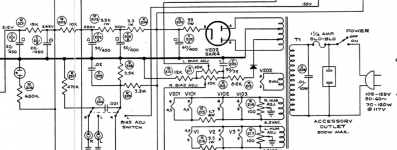
I found the schematic for the Scott 200 and I attach a screen shot of the power supply. The neon bulb and 680K current limiting resistor (R204) is across Section A of C201.
Attachments
Basing the circuit on the heather current level would seem more sensible: you do not need to apply the HT to detect the readiness of the amplifier
Might be fun to just hook a light bulb to the plate of a mini 7 pin sized thyratron, no relay. It seems thyratrons have found their purpose again in the light organ community!
Thyratrons | Threeneuron's Pile o'Poo
https://frank.pocnet.net/sheets/137/2/2D21.pdf
Thyratrons | Threeneuron's Pile o'Poo
https://frank.pocnet.net/sheets/137/2/2D21.pdf
Last edited:
I do have one of these in my collection. It should handle switching a light bulb or relay https://tubedata.altanatubes.com.br/sheets/077/1/1257.pdf
I do have one of these in my collection. It should handle switching a light bulb or relay https://tubedata.altanatubes.com.br/sheets/077/1/1257.pdf
😱 This made me realize any tube-based lamp driver wont work as an indicator, because it has to warm up too! Duh, my bad. This monster takes 15 minutes to warm up! A high impedance gate sense or the relay coil is looking better.
Doh I was going to suggest a thyratron earlier but you're right about the warmup. How about a cold cathode thyratron?
Oh that color organ circuit is really cool as well.
Oh that color organ circuit is really cool as well.
If you just want a light to come on when it's warmed up, Why not bias one of the pre-tubes with an LED?
Are you sure you want the (uncontrolled) impedance of the relay coil to be part of the cathode circuit? That would make me cringe more than a few transistors or a comparator.
What happens to the performance of the amp when the relay coil heats up? Is the voltage across the cathode resistor even within the spec of the relay? What happens when someone decides to 'roll' the input tube and that voltage changes?
As others have pointed out already, the better solution would be to sense the voltage across the cathode resistor with a comparator. You can build one pretty easily with a dual triode. It doesn't have to be super precise, it just has to give you an indication when the voltage across the cathode resistor rises above ground potential. But, as you point out, the comparator will need time for its heater to heat up before it becomes operational.
Solution: Change the "WARMUP" light to a "READY" light and connect it to the inverted output of the comparator. The light will turn on when the voltage across the cathode resistor exceeds some voltage and indicate that the amp is ready for use.
Personally, I would rather sense the heater current as that is outside the audio part of the circuit (unless you're dealing with directly heated tubes).
A simple alternative would be to use a time-delay relay. Connect the WARMUP bulb in series with a resistor across B+. Once the delay has expired, the time-delay relay shorts out the bulb. Now you have a 'free' bleeder resistor connected across B+, so you need to ensure that it can handle the power dissipated in it.
The drawback of this solution is that it operates open-loop, i.e., does not measure any variable within the circuit. But it does give the user indication that the amp is not ready for use quite yet. Just select the time-delay relay to have a delay that's longer than the warm-up time of the tube that's the slowest to warm up.
Tom
Last edited:
There should be a transistor detecting the voltage for the relay , not making the relay coil as cathode resistor ... the resistance of the coil is in the range of the actual cathode resistor so you have to measure and adjust the combination 😀
Last edited:
I've used a 6J1P connected as triode to control a relay. 250V B+ and a 110VDC relay (coil ~12k) in either the plate or cathode works. It was only controlling the relay though. It looks like you want to use an existing tube for it.
Basing the circuit on the heather current level would seem more sensible: you do not need to apply the HT to detect the readiness of the amplifier
^^^^^^^^ THAT.Personally, I would rather sense the heater current as that is outside the audio part of the circuit
As of cathode voltage sensing:
* leaves out *all* fixed bias amps.
* what cathode voltage do you set your trigger to?
Not sure it will be the exact same everyday, plus it will probably depend on +V which in due time depends on Mains voltage
Along time you will have to redjust it, tubes wear out, conditions change.
* won´t even comment on using a relay turn-on voltage as a voltage sensor plusnthe elephant in th room: where do you get a suitable relay?
They come in a series of preferred coil voltages .
So far detecting filment temperature (which is a PTC) is best, but even so we should detect actual cathode temp. which has a way longer time constant.
In all, measuring warm up time *once* and then setting up a timer, maybe with a little extra safety margin would best.
- Home
- Amplifiers
- Tubes / Valves
- Warm Up Indicator Circuit