Is there any other approach?all roads are leading to Rome
in many cases, cheapskate/dumpster diver approach is giving enormous joy


Now imagine me bringing... Uhm... 4, no, 8 microwave ovens from the dumpster.
I will say that I am building a new fusion reactor by using 8 magnetrons in a star configuration and a gram of Helium 3 as a fuel, maybe someone will believe and pay for that, so I can buy bigger speakers!
maybe it's a good idea to clarify thisin fact, I believe there is a way of doing it even better, mostly thinking of better Iq stability in dynamic domain
stiffer Iq with large signals and much faster recovery
oh well, can't always end with what's drawn on first napkin, sometimes second one is better
in short, out with optocoupler, in with current mirror
Warbler postponed to final version, whichever one ends as one
difference between (note C5, 470uF):
and (note C3, 470uF):
crucial part for integrating function of biasing mechanism is 470uF cap , which positive end is establishing voltage level for 100K, JFets gates biasing voltage; of course that JFets source is following gate voltage , thus establishing gate voltage level for big output part, setting Iq
in case of substantial voltage swing at output ( large signal condition), there are also large current changes through 0R22 sense resistors, so that's translating to changes in voltage across said 470uF
point is - when using optocoupler based circuit (pic 1) - level of integration stability is lower / changes of 470uF cap voltage are greater than in case of current mirror based circ (pic 2), and also ...... when large signal is over, recovery time that circuit is settled again to programmed Iq, with CM based circuit recovery time is much much faster
all of that being experience with Babelfish XA252, same as direct comparison between, say, SissySIT R.3 and SissySIT (42)
so, why not gilding da Lilly, when you can .....


Attachments
well, I did some more work these days than I was planning, so it seems tomorrow (today, past midnight) is Warbler day
ZM Strikes again, either Full Glory ..... or another Public Disgrace

ZM Strikes again, either Full Glory ..... or another Public Disgrace
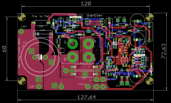
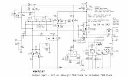
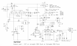
OK, as I promised - revised and (sorta, will explain later) final schematic
Forgot to bring ant pic-taking apparatus to workshop with me today, blissful silence of cellphone, when absent
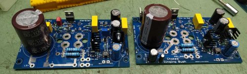
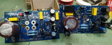
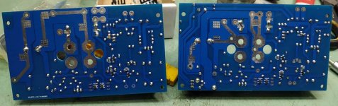
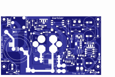
Anyway - pics of populated pcb shown in #28
Due to change in biasing circuit, it's now rock stable, in all manners - with temperature change, with rail change, big modulation etc.
I'm completely happy with revision
Forgot to bring ant pic-taking apparatus to workshop with me today, blissful silence of cellphone, when absent
Anyway - pics of populated pcb shown in #28
Due to change in biasing circuit, it's now rock stable, in all manners - with temperature change, with rail change, big modulation etc.
I'm completely happy with revision
Attachments
Last edited:
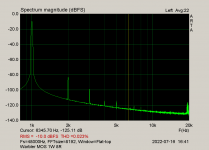
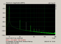
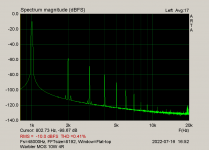
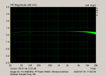
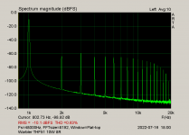
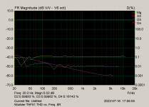
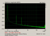
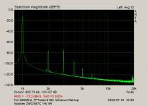
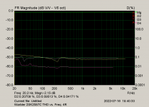
Pure Mos iteration
Everything the same as explained in start of the thread - same crummy choke ( uWave xformer primary) , negative rail aroundish 35Vdc, Iq 3A2
so, MOS, 8R load
Everything the same as explained in start of the thread - same crummy choke ( uWave xformer primary) , negative rail aroundish 35Vdc, Iq 3A2
so, MOS, 8R load
Attachments

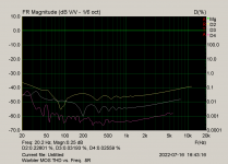


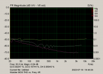
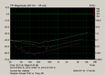
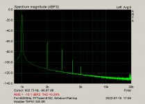
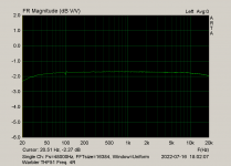
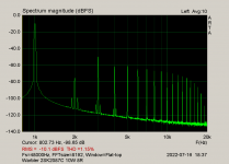
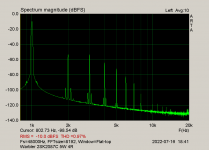
MOS Schade arrangement
R21 changed to 750R, R22 (18K) populated
8R load
R21 changed to 750R, R22 (18K) populated
8R load
Attachments
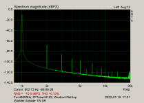


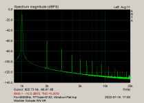


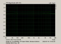
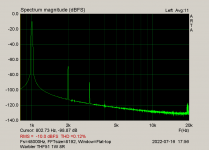
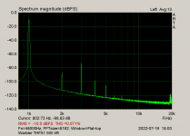
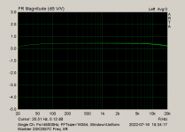
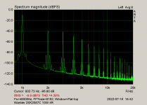
SIT arrangement, same conditions as above, THF51S as active device
8R load
8R load
Attachments
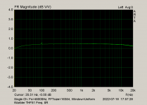


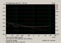
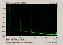
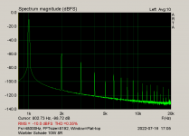
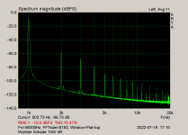
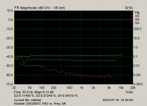
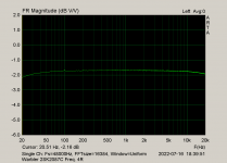
now, 2SK2087C as active element
negative rail decreased to -25V, Iq set at (moderate) 2A
that's ballpark really, not carved in stone - rail can be little lower or higher, Iq can be higher
I mean - my gut telling me that anything up to 70W of heat per one 2SK2087C is safe, as long it's properly cooled
which means - thin mica and proper ( not no-name) thermal goop, or 86/82 Keratherm pad; last one demanding torque wrench, 0.9Nm, to avoid uncontrollable squeeze of soft pad
so, 2SK2087C
8R load
Attachments

OK, as I promised - revised and (sorta, will explain later) final schematic
.........
later:
PowerUp/PowerOn thump just a little stronger than I can tolerate. In fact, nothing dangerous but I know that there would be difference - driving my 15" Tanns I know that thup is going to be naahwhocares, but with RCA of same size, them being almost microphone-like sensitive, thump would be ear-brain-nerve wracking, even if electrically benign
so m aking that change is gilding da lilly or matter of principle, whatever
so, decided to change pcb and incorporate thump eliminator (one small automotive relay and few itsybitsies), already proven in Choked Singing Bush ( that one still to come, really tried just function of said subcircuit)
will post some graphical amusement as soon I made pcb files with that; nice enjoyable evening in front of me, reading, drawing pcbs, some interesting movie - who can ask for more?
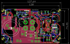
ok, here it is
final final
final
added relay across speaker output pads
during startup, relay/speaker is shorted for few seconds, so output cap is being charged through relay, not speaker coil; after that, relay is energized thus speaker left alone and free to sing
when powered Off, due to ultra small filter/smoothing cap in relay supply line (10uF), relay is momentary switched Off, thus shorting speaker coil and output cap is discharged through relay short
easy peasy
tomorrow, if not lazy, Choked Singing Bush; that one MOS Schade ( not interested in pure pentode MOS) and SIT - both THF51 and 2SK2087C
Attachments

- Home
- Amplifiers
- Pass Labs
- Warbler; Mos/Schade MOS/SIT choke loaded follower power amp