Been listening to a CCS-ed SIT follower for a while now and can no longer fight the itch to put it in an ugly case 🙂 Which prompts the possible replacement of the CCS with a choke as that promises less heatsink and less heat.
I see two options: LL2733 or LL2773. When one is parallel connected and the other series, both have about 100mH and work at 3.5A, leaving Rdc as the only apparent difference. 0.85ohms vs 0.44ohms. In a circuit where the bias current is limited by Rdc is it really safe to use the 0.44ohms? Is it even possible to predict? I know the 0.85ohm choke should be ok as Ben Mah used something similar...
I see two options: LL2733 or LL2773. When one is parallel connected and the other series, both have about 100mH and work at 3.5A, leaving Rdc as the only apparent difference. 0.85ohms vs 0.44ohms. In a circuit where the bias current is limited by Rdc is it really safe to use the 0.44ohms? Is it even possible to predict? I know the 0.85ohm choke should be ok as Ben Mah used something similar...
The voltage drop of the choke at the source only partly contributes to Vgs. The bias voltage applied to the gate also is part of Vgs. So if the voltage at the source is less due to the lower Rdc of the choke, the bias voltage at the gate can be increased to get the desired Vgs and Iq.
Sure, but the only current stabilising factor when using SITs seems to be the resistance of the choke. They do have a positive tempco at 3A, or did i get this wrong?
Ok, I see what you are saying. It depends on each individual SIT. Some SITs are stable and some are not, depending on their gate leak current. Some have low gate current and they are stable, whereas some have high gate leak current and they may run away. Fortunately most of my Tokins and VFETs have been manageable, and all except one were stable in common source mode with no source resistor and in common drain with choke at the source.
Zen Mod's SIT amp designs, both common drain and common source, eliminate the instability problem caused by high gate leak current.
Zen Mod's SIT amp designs, both common drain and common source, eliminate the instability problem caused by high gate leak current.
Zen Mod's SIT amp designs, both common drain and common source, eliminate the instability problem caused by high gate leak current.
Or too low choke dcr, which is my concern. My mistake asking this in ZM's thread, should have done this in your follower thread.
Zen Mod has specified 60mH 5A 0.47 Ohm RDC. As far as I know Hammond does not have a choke that meet those numbers. However I would venture to guess that the 193V would do the job.
Typical microwave oven transformers like AMR-803 (for 120vac mains) are typically 60mH and 0.5ohms and rated 10A. I have not used above 5A. This is what I used on MoFo and LuFo.


one thing is important - whatever you do, be sure that auxiliary supply is faster (than main PSU, to wake up) during powering-on sequence
in case of common type solutions ( secondary, rectifier, reg) that's doable having no bigger capacitances than needed
in case of voltage converters, it's up to you to determine how fast aux supply is
in case of common type solutions ( secondary, rectifier, reg) that's doable having no bigger capacitances than needed
in case of voltage converters, it's up to you to determine how fast aux supply is
So a dcdc with a lower startup voltage(like the one in the second link that has 4.5V startup voltage) would start faster. Will check how fast 🙂
Thanks.
Later edit. A cap multiplier in front of the amp can delay the power on sequence and the dcdc can be connected in front of the cap multiplier. This way the cap multiplier filters also the noise that comes from the dcdc.
Thanks.
Later edit. A cap multiplier in front of the amp can delay the power on sequence and the dcdc can be connected in front of the cap multiplier. This way the cap multiplier filters also the noise that comes from the dcdc.
Last edited:
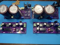
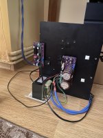
I managed to put two Warbler modules together and the power supplies for them.
On the power supply pcb I have a hf filter followed by a cap multiplier for the high current path. From the input I power also an isolated dcdc converter that generates -30V.
Now will need to test everything.
On the power supply pcb I have a hf filter followed by a cap multiplier for the high current path. From the input I power also an isolated dcdc converter that generates -30V.
Now will need to test everything.
Attachments
I tried both channels on the bench power supply. Both overshot to 0.5A as soon as I power them up then go to 0A and after a few seconds the bias starts to raise slowly to the preset value.
I connected in the system both channels and they both sing.
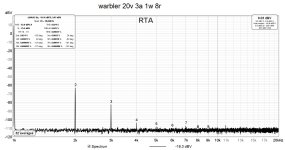
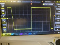
All good till now. Tomorrow I will do some ffts and a square wave test.
I connected in the system both channels and they both sing.
All good till now. Tomorrow I will do some ffts and a square wave test.
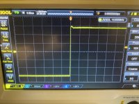
Everything seems in good shape.
Now it’s time to replace the heatsinks 🙂
A big thanks ZM !
Now it’s time to replace the heatsinks 🙂
A big thanks ZM !
Attachments


- Home
- Amplifiers
- Pass Labs
- Warbler; Mos/Schade MOS/SIT choke loaded follower power amp