First problem solved, dn2540 broken. Now even by inserting the load at the output, the voltage always remains constant at 5V. On R4 I read 240mV and on R9 50mV
I found another error, the pin4 connection of the opamp was not to GND. Now on R4 I measure 0.5V, on Pin3 of the opamp I measure 2.48V, on R13 I measure 1.2V. The output voltage is 5.22V
OPA1641 can't run on 5V with 2.5V ref or need a reference below 1.5V ,because of that, you don't have 5V at the output, but 5.22VHello. I use an OPA1641, on the R13 I measured 1.2V. before the dn2540 I measure 11.5V
Attachments
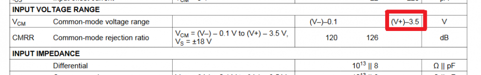
Sorry Grunf ,OPA1641 can't run on 5V with 2.5V ref or need a reference below 1.5V ,because of that, you don't have 5V at the output, but 5.22V
I do not understand why, could you explain to me, We have a 5v power supply and the reference is at 2.5v, within the 3.5v range of the data sheet, am I wrong to read?
(V+)-3,5V so it is 5-3,5=1,5V ,I recently made the same mistake 😉Sorry Grunf ,
I do not understand why, could you explain to me, We have a 5v power supply and the reference is at 2.5v, within the 3.5v range of the data sheet, am I wrong to read?
Yes, I used LT6202 for 5V and now I tried ADA4896 and I can say that it is excellent or lower the reference voltageSo is it better to change opamp or lower the reference voltage?
Is there a significant loss of performance by lowering the reference voltage? To lower the voltage is it enough to increase the resistance from 150R?Sì, ho usato LT6202 per 5V e ora ho provato ADA4896 e posso dire che è ottimo o abbassare la tensione di riferimento
Last edited:
Unfortunately no, you should change the type of LED and maybe the pnp transistor, I haven't tried it so I can't guarantee anything.Is there a significant loss of performance by lowering the reference voltage? To lower the voltage is it enough to increase the resistance from 150R?
So far, it is easier to change the op.amp.
Opamp replaced with an AD817, stable output voltage at 4.97V. Voltage on R4 1V as per Walt Jung specifications, on Pin3 of the opamp 2.48V. I think we are there, can these 0.03V missing at the output affect?Unfortunately no, you should change the type of LED and maybe the pnp transistor, I haven't tried it so I can't guarantee anything.
So far, it is easier to change the op.amp.
The difference is less than 1%, which is great, so there are no problems with the output voltage of 4.97V.
Perfect, now I will test it in conditions of continuous use to check that there are no problems, in the meantime I will start the construction of the negative board. The last step will be to optimize the final pcb, shortening the connections. Do you have any suggestions?The difference is less than 1%, which is great, so there are no problems with the output voltage of 4.97V.
Hello
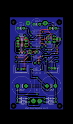
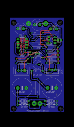
Here is the final pcb, I changed the arrangement of the components to shorten the tracks as much as possible, I added two cap to the power lines, in the positive rail we have an rc filter. I corrected the sizing of the Dale resistors, which were bigger, The inputs and outputs are intentionally without connectors, I always prefer to solder the wires directly. The dimensions are the same about 5x8 cm. Any further advice is welcome.
Here is the final pcb, I changed the arrangement of the components to shorten the tracks as much as possible, I added two cap to the power lines, in the positive rail we have an rc filter. I corrected the sizing of the Dale resistors, which were bigger, The inputs and outputs are intentionally without connectors, I always prefer to solder the wires directly. The dimensions are the same about 5x8 cm. Any further advice is welcome.
Attachments

Thanks for your tips, I'll take them into consideration.
I would like to implement the cascode of dn2540 , could that make a difference? Did I use a different component, even smd could it still improve things?
I would like to implement the cascode of dn2540 , could that make a difference? Did I use a different component, even smd could it still improve things?
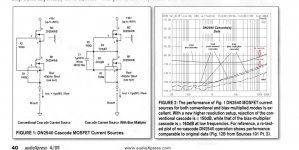
Waiting to order the new pcb, I was looking for further improvements to the circuit, and I was wondering how useful it would be to implement a cascode with bias multipler. From Mr. Jung's writings we notice an improvement of 10dB at low frequency compared to a classic cascode.
Attachments
Can You please share that small version of pcb in Eagle format and last version? What about preformance in analog sections or analog circuits?. Did You try it in that way?Tix88, small guidelines from me, this is my last PCB for WJ shunt, dimensions are 40X30mm, single sided PCB with ground plane.
I had already added CCS with 2SK246 for LM4040 which was later replaced with GLED431. Also the 100uF located next to the LM4040 should be UKZ 100uF / 25V so it needs a little more space.
the lower device must have an idss higher than the selected current or parallel a couple of them. With unselected 2SK170 BL a 500 ohm trimpot gave 2ma with good accuracy.
Cascode with bias multipler I mentioned the page before and gave an example with BSP149 and BSS159, otherwise a very good upgrade.Waiting to order the new pcb, I was looking for further improvements to the circuit, and I was wondering how useful it would be to implement a cascode with bias multipler. From Mr. Jung's writings we notice an improvement of 10dB at low frequency compared to a classic cascode.
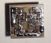
btw; I made a new test PCB, 32x35mm, all resistors are MELF0204 except R1,2 which are RN55 and two 1R which I will replace with 1W MELF in the future.
This version has the same ,cascode with bias multipler but slightly different reference and OPA1641 which now works great.
Attachments
- Home
- Amplifiers
- Power Supplies
- Walt Jung shunt Design