I recently purchased two mystery VU meters from Amazon that I’d like to install in my F6 (I'd link to the ones I bought but they are no longer available). I’d like to drive these meters off the amplifier inputs rather than across the speaker outputs. The meter looks like a Sifam presentor meter, but it doesn’t react to an AC signal w/ a 3.6K resistor in-line, as the Sifam meter claims it should. It seems the meter does not have internal rectification.
So I purchased a JLM audio VU2 stereo buffer PCB kit. I don’t have a schematic for the kit but it includes a dual op-amp, adjustable potentiometers, and diodes to rectify the AC signal to DC. Conveniently, it also has headers to provide 12VDC to the lamps in the meters.
The meter works with the buffer kit (I did have to replace two 3k3 ohm resistors with 680 ohm resistors on the buffer PCB to provide more gain, per Note 3 here in the build instructions) but it appears to respond in a linear, rather than a logarithmic fashion.
The problem of course is that the meters react barely - or not at all - at normal listening levels and peg during loud peaks at medium-to-load listening levels. What I’d like to do is to create a logarithmic circuit in-line between the buffer board and the meter that will compress the range of the meter across a wider range of input signals so that the both quiet and load signals read on the meter. Something similar to what is proposed here, but tailored to the specifications of the meters in question and designed for a (much) lower-level signal rather than the speaker-output signal.
I’m hoping that folks here might be able to let me know whether it is even possible to create a similar circuit w/ diodes for such a significantly lower range of input voltages and run it in-line with the buffer kit. I’m still relatively new to this hobby and currently working my way through the Art of Electronics but I haven’t learned enough yet to solve this problem on my own.
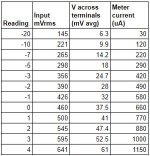
I took a bunch of measurements of the meter being fed a 1KHz signal from my DAC/preamp through the buffer board. I measured the current being fed into the meter, the average voltage across the meter terminals, and the RMS voltage of the input signal into the buffer board. (I took a few other measurements, all of which can be seen in this Google spreadsheet).
It seems the meter has an internal resistance of around 50-60 ohms. It measures ~51 ohms with a multimeter. Based on the measured Vavg values across the terminals correlated with the measured current the impedance at 1KHz is ~59 ohms. It appears to reach full deflection with 1.15mA of current and a +3 reading with exactly 1mA.
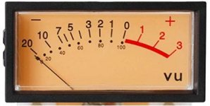
I've attached a table of measurements and some charts (the scale is a bit weird given the VU measurements, forgive me) as well as an image of the front face of the meter.
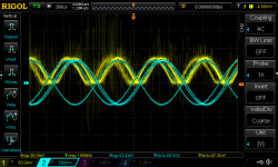
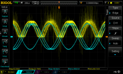
I've also attached two screenshots from the scope. One shows the meter at VU reading 0 - yellow trace is the signal across the meter terminals after rectification by the buffer board. The blue trace is the input signal to the buffer board. Note the different scales and readings. The second shows the same at reading +3 (nearly full deflection).
So I purchased a JLM audio VU2 stereo buffer PCB kit. I don’t have a schematic for the kit but it includes a dual op-amp, adjustable potentiometers, and diodes to rectify the AC signal to DC. Conveniently, it also has headers to provide 12VDC to the lamps in the meters.
The meter works with the buffer kit (I did have to replace two 3k3 ohm resistors with 680 ohm resistors on the buffer PCB to provide more gain, per Note 3 here in the build instructions) but it appears to respond in a linear, rather than a logarithmic fashion.
The problem of course is that the meters react barely - or not at all - at normal listening levels and peg during loud peaks at medium-to-load listening levels. What I’d like to do is to create a logarithmic circuit in-line between the buffer board and the meter that will compress the range of the meter across a wider range of input signals so that the both quiet and load signals read on the meter. Something similar to what is proposed here, but tailored to the specifications of the meters in question and designed for a (much) lower-level signal rather than the speaker-output signal.
I’m hoping that folks here might be able to let me know whether it is even possible to create a similar circuit w/ diodes for such a significantly lower range of input voltages and run it in-line with the buffer kit. I’m still relatively new to this hobby and currently working my way through the Art of Electronics but I haven’t learned enough yet to solve this problem on my own.
I took a bunch of measurements of the meter being fed a 1KHz signal from my DAC/preamp through the buffer board. I measured the current being fed into the meter, the average voltage across the meter terminals, and the RMS voltage of the input signal into the buffer board. (I took a few other measurements, all of which can be seen in this Google spreadsheet).
It seems the meter has an internal resistance of around 50-60 ohms. It measures ~51 ohms with a multimeter. Based on the measured Vavg values across the terminals correlated with the measured current the impedance at 1KHz is ~59 ohms. It appears to reach full deflection with 1.15mA of current and a +3 reading with exactly 1mA.
I've attached a table of measurements and some charts (the scale is a bit weird given the VU measurements, forgive me) as well as an image of the front face of the meter.
I've also attached two screenshots from the scope. One shows the meter at VU reading 0 - yellow trace is the signal across the meter terminals after rectification by the buffer board. The blue trace is the input signal to the buffer board. Note the different scales and readings. The second shows the same at reading +3 (nearly full deflection).
Attachments
-
 table_of_data.JPG34.3 KB · Views: 750
 -
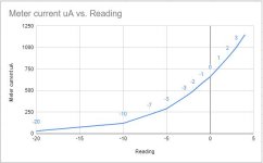 current_vs_reading.JPG29.3 KB · Views: 714
 -
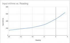 input_v_vs_reading.JPG25.7 KB · Views: 693
 -
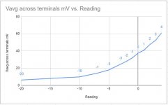 v_terminals_vs_reading.JPG28.7 KB · Views: 664
 -
 VU_meter_0_position_1.png81.6 KB · Views: 714
 -
 VU_meter_3_position.png88.9 KB · Views: 267
 -
 meter_face.JPG23.4 KB · Views: 341
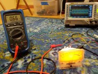
Oh, and here's a pic measuring the current into the meter at a 0 VU reading while also measuring the input signal and output signal of the amplifier across an 8ohm dummy load (a VU 0 reading in my case corresponded to .26W out of the ACA amplifier - which is pretty loud in my room with my speakers 😀).
Attachments
> the meters react barely - or not at all - at normal listening levels and peg during loud peaks at medium-to-loud listening levels.
That's what a VU meter does. That is what it is FOR. You want to run your radio transmitter at 99% modulation. You want to watch the LOUD parts of the program. The soft parts, as long as they are in proportion, you don't really care. (Anyway a low-cost log-scale meter was not practical in 1938.)
Which does open the question "why" you want meters, if not to warn of impending overload (which they are not that good at, especially with hard-clip channels).
At this point you are buying/building/designing more and more stuff to make these meters work different. If you do make them log, technically you should print new scales with linear dB. Or BBC-type units.
I wonder if you go back to Amazon if you might find a complete package you like better.
Amplifier Board SCM Stereo Level indicator VU
Dual 30 Level Indicator VU Meter Stereo Amplifier Board with AGC
Dual 12-bit Music Level Indicator Adjustable Light Speed VU Meter with AGC
Obviously some of these vendors do not have a clue. ("Garden"??)
The 10-cent logger is a Silicon diode. Here it is expedient to use it with a 19 cent opamp.
Even a diode is loggy past 40dB of current. In precision work the tempco is distressing, then the parasitic resistances. But in a shirt-sleeve listening room it is not bad. And "improved" loggers are an endless tunnel. And the part we used to use for primary correction is out of style (production?). An uncorrected penny diode is about 1dB error for 5 degrees C temperature shift. Graph shows 68F to 86F has error, but not large in relation to musical dynamics and varying listening levels. The parasitic leakage actually "extends the tail" so even signal 90dB down will twitch a little.
The first image is a DC run to check the curve. The second is AC. A cap across the meter is probably needed to smooth the motion. The value has to be set by experiment, with 1uFd to 100uFd the probable range. I'd start with a socketed TL072 opamp. It will not be accurate at 20kHz and -60dB but most speech/music power is below 1kHz and the application does not seem to need high accuracy. And TL072 will tolerate a somewhat sloppy build. All the usual app-notes still apply: power bypass, input DC block.
Attachments
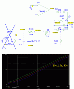
PRR - thank you for your replies and for the schematic / sims. You've given me an excellent jumping off point to experiment. I'm curious - what program did you use to run these? You have inspired me to learn to use one. I know folks on this forum use LTSpice and so I've started playing around with it a bit.
To answer your question as to why I want meters if not for a VU meter's intended purpose - eye candy, mostly. I like the analog meter movement. If I can calibrate the meter such that its values correspond to the actual output power of the amp, with +3 representing the maximum output just before clipping, then that's all the better. I like the display on this Mitsubishi DA-M10 power meter which scales from .001 Watts to 200 Watts, the max output of the amplifier for which it was intended.
I'm curious about the device in the schematic labeled 'Potset' -- is that just a device to simulate the different signal amplitudes (1mV, 10mV, 100mV, 1mV) being fed into the circuit sim, like a simulated potentiometer?
Again, appreciate your help.
Chinese mini VU Meters
At post #28 I published a Vu meter driver I made for a microphone preamplifier.
It monitors its balanced output on the XLR .
At post #28 I published a Vu meter driver I made for a microphone preamplifier.
It monitors its balanced output on the XLR .
Read A simple passive logarithmic VU-meter
This does what you want.
Passive Stereo VU Meter Driver Board Audio Amplifier DB Audio Level Meter (L49) | eBay
I think tihs one follow schematic
This does what you want.
Passive Stereo VU Meter Driver Board Audio Amplifier DB Audio Level Meter (L49) | eBay
I think tihs one follow schematic
Last edited:
First, a VU meter is for line level signals that you dont constantly vary, ie a tape input where you want the level to stay the same, around 0VU or in a preamp befre the volume control. Real (pro) VU meters are for pro level signals which are around 10db hotter than consumer and seeing the xlr inputs my guess is that is part of the problem, but its a guess, you need to find the specs for the driver circuit. The other problem is that a 0Vu signal will drive your amp close to full power. So normal listening levels of about 1 watt are 20db (30db for pro meters) down and will barely move your meters. You need to add a bunch of gain, but how much will depend on how loud you listen.
Last edited:
To answer your question as to why I want meters if not for a VU meter's intended purpose - eye candy, mostly. I like the analog meter movement. If I can calibrate the meter such that its values correspond to the actual output power of the amp, with +3 representing the maximum output just before clipping, then that's all the better. I like the display on this Mitsubishi DA-M10 power meter which scales from .001 Watts to 200 Watts, the max output of the amplifier for which it was intended.
Again, appreciate your help.
Yes you would be better off with a power meter because that one has over 50 db of range, see the problem with a vu meter?
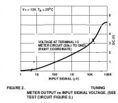
If you want a large range and don't care about the utmost accuracy, you can use a so-called RSSI circuit: a chain of gain stages that clip in a predictable manner, each with its own rectifier, and with a summing circuit that sums or averages all the rectifier outputs. FM IF ICs (like the quite old CA3089 and its slightly more modern variants) often have such a circuit on chip. Attachment: CA3089 tuning meter output voltage versus IF input level.
Attachments
> use a so-called RSSI circuit
Actually a result, not a method.
Yes; a chain of gain stages is surely more accurate in wide range of temperatures. But it is a lot of parts.
Gain of 3 or 4 (10-12dB) per stage is as much as you can go without lumps. So a 60dB range (to cover the dynamics of domestic listening) is like 6 amplifiers and 6 rectifiers, plus summing. I never figured how to easily make the '3089 read audio (it has internal caps) but no matter because they are long gone. A couple of the special-chip companies offer RSSI chips, but being low/no-demand the prices tend to be high and delivery spotty.
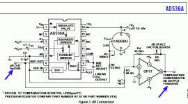
AD536A is one, and DigiKey has hundreds at $20.
https://www.analog.com/media/en/technical-documentation/data-sheets/AD536A.pdf
This is an actual logger, not a clip-chain. (Hmmm, and it still needs a compensation resistor...)
Actually a result, not a method.
Yes; a chain of gain stages is surely more accurate in wide range of temperatures. But it is a lot of parts.
An externally hosted image should be here but it was not working when we last tested it.
Gain of 3 or 4 (10-12dB) per stage is as much as you can go without lumps. So a 60dB range (to cover the dynamics of domestic listening) is like 6 amplifiers and 6 rectifiers, plus summing. I never figured how to easily make the '3089 read audio (it has internal caps) but no matter because they are long gone. A couple of the special-chip companies offer RSSI chips, but being low/no-demand the prices tend to be high and delivery spotty.
AD536A is one, and DigiKey has hundreds at $20.
https://www.analog.com/media/en/technical-documentation/data-sheets/AD536A.pdf
This is an actual logger, not a clip-chain. (Hmmm, and it still needs a compensation resistor...)
Attachments
Actually you link to an RMS to DC converter instead of a logarithmic converter.
The lower cut-off frequency of the CA3089 and similar circuits is set by external decoupling capacitors, for the CA3089 those between pins 2 and 3 and from 3 to ground. You will need a quite large capacitor because the input resistance is 30 kohm/(gain of the limiter chain + 1).
The lower cut-off frequency of the CA3089 and similar circuits is set by external decoupling capacitors, for the CA3089 those between pins 2 and 3 and from 3 to ground. You will need a quite large capacitor because the input resistance is 30 kohm/(gain of the limiter chain + 1).
> CA3089 and similar circuits is set by external decoupling capacitors,
http://www.radioradar.net/en/files.html?fid=49163
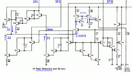
I may be wrong, again. But I can't see how the "Peak Detectors" of the LM3089 work except via the 3pFd caps. These are reasonably low-Z at 10MHz but "open" for audio. Short breadboard trial didn't work either (but details are dim after all the lost years).
http://www.radioradar.net/en/files.html?fid=49163
I may be wrong, again. But I can't see how the "Peak Detectors" of the LM3089 work except via the 3pFd caps. These are reasonably low-Z at 10MHz but "open" for audio. Short breadboard trial didn't work either (but details are dim after all the lost years).
Attachments
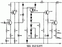
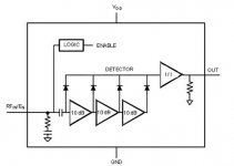
The NE/SA604 works quite well as a log detector: it has an 80dB range:
https://www.nxp.com/documents/application_note/AN1991.pdf
And it is still available:
SA604 | Mouser Electronics, Inc. Nederland
https://www.nxp.com/documents/application_note/AN1991.pdf
And it is still available:
SA604 | Mouser Electronics, Inc. Nederland
Attachments

Last edited:
Hey folks just wanted to drop a quick note to say thanks one again for all the suggestions.
I'm putting in a parts order for another project this week; I'm going to give the simple diode & opamp circuit proposed by PRR a try first.
Having the additional range / sensitivity that and RSSI chip like the SA604 offers is intriguing and possibly a next step but as I said - I'm a newbie - so designing a circuit around one of those chips will require some additional study and time investment on my part.
- Home
- Design & Build
- Parts
- VU meter and buffer circuit for amp - compressing readings logarithmically