The 10-cent logger is a Silicon diode. Here it is expedient to use it with a 19 cent opamp.
Even a diode is loggy past 40dB of current. In precision work the tempco is distressing, then the parasitic resistances. But in a shirt-sleeve listening room it is not bad. And "improved" loggers are an endless tunnel. And the part we used to use for primary correction is out of style (production?). An uncorrected penny diode is about 1dB error for 5 degrees C temperature shift. Graph shows 68F to 86F has error, but not large in relation to musical dynamics and varying listening levels. The parasitic leakage actually "extends the tail" so even signal 90dB down will twitch a little.
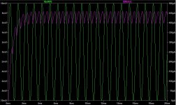
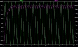
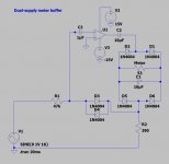
The first image is a DC run to check the curve. The second is AC. A cap across the meter is probably needed to smooth the motion. The value has to be set by experiment, with 1uFd to 100uFd the probable range. I'd start with a socketed TL072 opamp. It will not be accurate at 20kHz and -60dB but most speech/music power is below 1kHz and the application does not seem to need high accuracy. And TL072 will tolerate a somewhat sloppy build. All the usual app-notes still apply: power bypass, input DC block.
I have been learning LTspice and set out to simulate the circuit that PRR suggested. I am wondering if I have made a mistake in the model - as the behavior doesn't quite match what I was expecting. Excuse me if I have made a newbie mistake.
I attached the model and some screenshots. With 10mV in I get only 450uA of current, with 100mV I get 800uA and with 1V I get about 1.1mA. (Am I misunderstanding / was this intended for speaker-level outputs rather than line level inputs...?)
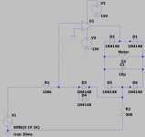
I used different diodes in the sim but they have the same forward voltage drop (~1V) as the ones suggested.
Any suggestions as to what I might be misunderstanding or doing wrong?
Attachments

> different diodes in the sim but they have the same forward voltage drop (~1V)
"1V" is a max, even a reject limit, found on most diode datasheets.
The 1N400x 1-Amp rectifier is much large than the 1N4148/1N914 detector, so lower voltage at the same current, and that may be much of the difference.
I don't see a problem with your sim. It is logging. Both plans have the problem that there is no "zero trim", no for-sure input which will read zero on the meter. (Also, this simple logger will read "below zero" for very very small inputs.)
Build it. Increasing the "300r" will stop the meter banging on the right pin. Increasing or decreasing the "100k" will adapt it for bigger or smaller inputs.
Attachments
Thanks PRR. I'll report back once I've given it a try. I am going to try a version the simple passive circuit as well.
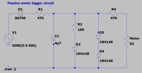
I've built up a version of both the passive circuit and the op-amp buffer circuit on breadboard and have been comparing the results with my two meters side-by-side operating simultaneously.
I have the op-amp buffer across the line-level input and the passive circuit across the speaker-level output. I had to significantly tweak the resistor values in the passive circuit to get adequate sensitivity. I also tweaked the resistor values a bit in the op-amp circuit.
I've attached schematics of the actual circuits built. The op-amp buffer and the passive buffer needles begin moving at around the same input level but the op-amp buffer has much greater range of the pointer swing. I quite like it. I've been testing them with my ACA driven by a DAC.
At 1W of amplifier output the op-amp buffer reads about +1 and the passive buffer reads 0. But a much lower output value corresponds to a much higher reading on the VU meter driven by the op-amp. For example a reading of -3 on the op-amp buffer corresponds to 9mW amplifier output. The same -3 reading on the passive buffer corresponds to 200mW amplifier output on the passive buffer.
While testing, I noticed that the op-amp buffer is attenuating the signal a bit (for example, if I have 4.97V across the speaker dummy load without the buffer across the input that voltage drops to 4.86V when the buffer is added across the input).
I was unable to plainly hear any added distortion with either buffer solution although I've read of problems with each of these solutions: for the op-amp buffer, dirty ground current (see Objective Sound article, which he also posted here) and for the passive meter, distortion especially at low-levels due to the diode being across the speaker. I was unable to visibly see any distortion with my oscilloscope but I haven't checked with a proper RTA.
So a question about the two circuits: in the op-amp buffer, given that my input signal ground is shared with the PSU ground and the meter current is also being dumped there via the 390 Ohm resistor (R2 in the schematic) - is there cause for concern vis-a-vis distortion? Is the attenuation of the input signal simply related to having a the 47K+ load across the input? (FWIW, my multimeter measures 5Mohm across the meter inputs in the case of the op-amp buffer and 4.8Kohm into the passive buffer.)
Am I correct in assuming that the op-amp buffer will still create less distortion overall than the passive buffer?
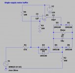
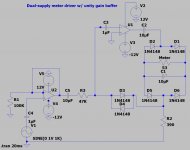
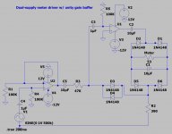
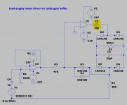
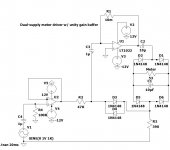
Another hopefully simple question: I'd like to use a 12VDC single supply w/ virtual ground to drive this, rather than building a dual-rail supply (see attached schematic). Works fine in the LTSpice simulation. Haven't tried it in the real world yet. Anything I should be concerned with there?
Appreciate all the help everyone has offered so far. This has been my first time building an op-amp circuit, using LTSpice -- even using a breadboard! Been learning a lot.
I have the op-amp buffer across the line-level input and the passive circuit across the speaker-level output. I had to significantly tweak the resistor values in the passive circuit to get adequate sensitivity. I also tweaked the resistor values a bit in the op-amp circuit.
I've attached schematics of the actual circuits built. The op-amp buffer and the passive buffer needles begin moving at around the same input level but the op-amp buffer has much greater range of the pointer swing. I quite like it. I've been testing them with my ACA driven by a DAC.
At 1W of amplifier output the op-amp buffer reads about +1 and the passive buffer reads 0. But a much lower output value corresponds to a much higher reading on the VU meter driven by the op-amp. For example a reading of -3 on the op-amp buffer corresponds to 9mW amplifier output. The same -3 reading on the passive buffer corresponds to 200mW amplifier output on the passive buffer.
While testing, I noticed that the op-amp buffer is attenuating the signal a bit (for example, if I have 4.97V across the speaker dummy load without the buffer across the input that voltage drops to 4.86V when the buffer is added across the input).
I was unable to plainly hear any added distortion with either buffer solution although I've read of problems with each of these solutions: for the op-amp buffer, dirty ground current (see Objective Sound article, which he also posted here) and for the passive meter, distortion especially at low-levels due to the diode being across the speaker. I was unable to visibly see any distortion with my oscilloscope but I haven't checked with a proper RTA.
So a question about the two circuits: in the op-amp buffer, given that my input signal ground is shared with the PSU ground and the meter current is also being dumped there via the 390 Ohm resistor (R2 in the schematic) - is there cause for concern vis-a-vis distortion? Is the attenuation of the input signal simply related to having a the 47K+ load across the input? (FWIW, my multimeter measures 5Mohm across the meter inputs in the case of the op-amp buffer and 4.8Kohm into the passive buffer.)
Am I correct in assuming that the op-amp buffer will still create less distortion overall than the passive buffer?
Another hopefully simple question: I'd like to use a 12VDC single supply w/ virtual ground to drive this, rather than building a dual-rail supply (see attached schematic). Works fine in the LTSpice simulation. Haven't tried it in the real world yet. Anything I should be concerned with there?
Appreciate all the help everyone has offered so far. This has been my first time building an op-amp circuit, using LTSpice -- even using a breadboard! Been learning a lot.
Attachments
> the op-amp buffer is attenuating the signal a bit
Your numbers suggest you are driving with a source impedance a hair over 1k. (The working input Z is essentially the 47k resistor; I dunno why your DMM says what it says.) Obviously if you had a "zero" impedance source there would be zero loading. The loading alone won't matter, and the log-amp will be fairly linear at low audio frequencies, but could glitch at the top of the audio band. You could add a unity gain non-inverting opamp and buffer this away.
A single-supply version not only needs a Vref to bias, it has to be very stiff to absorb the meter current. Stuff "like" this is normally better with true split supply.
Your sim plan should NOT work, even in SPICE, because there is no DC return at U1 -In, and the opamp will quickly de-bias itself. Even for an "IDEAL" opamp this is a FAIL; no matter, because the Ideal opamps are never in stock when you need one. But a good start.
Last edited:
Your sim plan should NOT work, even in SPICE, because there is no DC return at U1 -In, and the opamp will quickly de-bias itself. Even for an "IDEAL" opamp this is a FAIL; no matter, because the Ideal opamps are never in stock when you need one. But a good start.
Appreciate the quick reply - I'll spend some more time working on understanding and simulating a single-supply version.
That said - I have a spare transformer I could use to make a dual rail PSU. I'd just rather not put a second power transformer inside my F6 chassis. May need to mount it externally and just bring DC in.
As always I appreciate the help and comments, PRR.
I took a crack at adding a unity gain buffer to the circuit.
I also purchased one of these units that provides +/- 12V from a DC wall wart.
I also purchased one of these units that provides +/- 12V from a DC wall wart.
Attachments
All opamp input pins need a path for DC at each input.
EDIT: an "IDEAL" opamp may "do a right thing" with DC-open input. My SPICE will. Using a "real" (simulated) LM324 opamp gives other readings, some not even realistic. The models are NOT valid for all mis-use. (However a PNP-in opamp should not drive an open input to the negative rail, as the model I have does; nor drive a 1000Meg input resistor to >50V above the positive rail.)
EDIT: an "IDEAL" opamp may "do a right thing" with DC-open input. My SPICE will. Using a "real" (simulated) LM324 opamp gives other readings, some not even realistic. The models are NOT valid for all mis-use. (However a PNP-in opamp should not drive an open input to the negative rail, as the model I have does; nor drive a 1000Meg input resistor to >50V above the positive rail.)
Attachments
Last edited:
Got it, thank you PRR. I found this article very helpful in explaining the point you made about needing a DC return path for each of the pins.
I've added one to the second op-amp as well in the attached schematic.
I've added one to the second op-amp as well in the attached schematic.
Attachments
OK, now:
What does R1 do for us? (Nothing.)
Why do you take a signal at DC Zero, capacitor-block it, then resistor-reference it back to DC zero? This is left-over from when you were DC-referencing half the supply on a single-supply plan. But this plan is dual supply, so should not be needed. (We make an exception for the input to the box, because the external source may be leaking unknown DC.)
Attachments
So - I breadboarded the circuit with the unity gain buffer for the first time. I followed your recommendations and removed the unnecessary caps and resistors.
However - and I noticed this same thing before I added the unity gain buffer - C2, the capacitor on the output pin of the second opamp, is necessary to the correct functioning of the circuit. Without it, I noticed the meter pin would rest, twitching slightly, around -7dB, even during silent passages or with a shorted input.
At first I thought this might be explained by the cap operating as a high-pass filter in conjunction with R2 and that there was some ripple or hum from the PSU getting amplified somehow. I experimented with different value caps - .1uF, 1uF, 10uF, and 200uF. The .1 - 10uF behave the same (although the .1uF significantly reduces the reading on the meter with a 60Hz tone on the input). The 200uF behaved as though there was no capacitor on the output at all: needle still resting at around -7dB.
Then I decided to hook up the scope to see what was really going on. Seems that - even though there's no DC offset on the inverting pin and the non-inverting pin is grounded - there's a significant amount of offset on the output of U1.
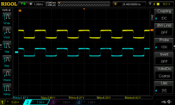
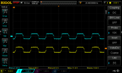
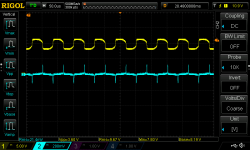
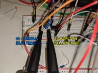
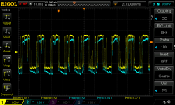
I did some experimenting. In the first of the two attached screenshots I have the yellow probe attached to the output of U1 and the blue probe attached to the opposite leg of C2 (see attached photo). The first is a 500Hz tone if memory serves. You can see about +8V DC offset on the output of U1. In the second of the two attached screenshots I am putting a 15Khz tone on the input. I watched the output offset drift from the positive (where it rests with no signal) into the negative. You can see that the DC offset is at about -8V in the second screenshot.
So I wanted to ensure there was no offset on the input pin. The third screenshot shows the blue trace on the input pin of U1 and the yellow trace on the output pin with a 15Khz test tone.
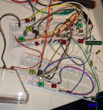
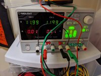
I am running the circuit off a dual-rail supply from my bench psu (see photo). It's configured so that the '-' supply of the first output channel is shorted to the '+' supply of the second channel. This is my ground reference for the circuit. The first '+' output provides my positive rail and the second '-' output provides my negative rail.
I scoped the unity gain opamp buffer as well and the input and ouput are identical, as expected, with no DC offset. The power supply configuration for that is exactly the same.
I'm sure I'm missing something obvious to a more experienced person here -- but I'm pretty confused as to why the offset is drifting so much on the second op-amp. Could it be that all these messy jumpers and other cables acting as antennas are causing problems and that the circuit would behave much better on a proper PCB with shorter traces? Are you absolutely sure you don't have any ideal op-amps in your stash to send my way so that the real circuit behaves as simulated? 😀
Either way, the cap on the output seems to do a satisfactory job of solving the problem for bouncy needle joy.
Thanks again for all your help thus far.
However - and I noticed this same thing before I added the unity gain buffer - C2, the capacitor on the output pin of the second opamp, is necessary to the correct functioning of the circuit. Without it, I noticed the meter pin would rest, twitching slightly, around -7dB, even during silent passages or with a shorted input.
At first I thought this might be explained by the cap operating as a high-pass filter in conjunction with R2 and that there was some ripple or hum from the PSU getting amplified somehow. I experimented with different value caps - .1uF, 1uF, 10uF, and 200uF. The .1 - 10uF behave the same (although the .1uF significantly reduces the reading on the meter with a 60Hz tone on the input). The 200uF behaved as though there was no capacitor on the output at all: needle still resting at around -7dB.
Then I decided to hook up the scope to see what was really going on. Seems that - even though there's no DC offset on the inverting pin and the non-inverting pin is grounded - there's a significant amount of offset on the output of U1.
I did some experimenting. In the first of the two attached screenshots I have the yellow probe attached to the output of U1 and the blue probe attached to the opposite leg of C2 (see attached photo). The first is a 500Hz tone if memory serves. You can see about +8V DC offset on the output of U1. In the second of the two attached screenshots I am putting a 15Khz tone on the input. I watched the output offset drift from the positive (where it rests with no signal) into the negative. You can see that the DC offset is at about -8V in the second screenshot.
So I wanted to ensure there was no offset on the input pin. The third screenshot shows the blue trace on the input pin of U1 and the yellow trace on the output pin with a 15Khz test tone.
I am running the circuit off a dual-rail supply from my bench psu (see photo). It's configured so that the '-' supply of the first output channel is shorted to the '+' supply of the second channel. This is my ground reference for the circuit. The first '+' output provides my positive rail and the second '-' output provides my negative rail.
I scoped the unity gain opamp buffer as well and the input and ouput are identical, as expected, with no DC offset. The power supply configuration for that is exactly the same.
I'm sure I'm missing something obvious to a more experienced person here -- but I'm pretty confused as to why the offset is drifting so much on the second op-amp. Could it be that all these messy jumpers and other cables acting as antennas are causing problems and that the circuit would behave much better on a proper PCB with shorter traces? Are you absolutely sure you don't have any ideal op-amps in your stash to send my way so that the real circuit behaves as simulated? 😀
Either way, the cap on the output seems to do a satisfactory job of solving the problem for bouncy needle joy.
Thanks again for all your help thus far.
Attachments
-
 opamp_buffer_circuit_as_built.JPG84.1 KB · Views: 315
 -
 pic_of_meter.jpg452.4 KB · Views: 279
 -
 DS1Z_QuickPrint12.png37.7 KB · Views: 267
 -
 DS1Z_QuickPrint13.png38.7 KB · Views: 256
 -
 DS1Z_QuickPrint16.png39.7 KB · Views: 136
 -
 buffer_bench_supply.jpg683.1 KB · Views: 145
 -
 scope_probes.jpg675.2 KB · Views: 162
Last edited:
Ah, pesky DC offset error.
Without the cap the log-amp runs at high ("infinite") gain and you may want to null the offset. Feed a pot with +/-12V, take the wiper to the - input with maybe a 10Meg resistor.
WITH that cap there is NO DC feedback around the opamp and it will wander-off forever. Tie a 10Meg resistor from Out to -In so it self-corrects. (Ah, and then it will also help to put-back the cap in series with the 47k so opamp DC gain goes to unity.)
Serious log-amp development gets to be a lot of tricks and hacks and strayinsights.
Wow, PRR -- it works!
The sim doesn't like it for some reason but I went ahead and built the circuit as you described in the second scenario -- with a 10M resistor from the Out to the -In and both caps in place (the 1uF on the input and the 10uF on the output).
When I first power on the amp with the scope set up as before - one channel on the ouput and the other on the opposite leg of C2 - I can see the output offset wander for a short while (maybe 20 seconds) until eventually it settles. Meter movement remains the same as before.
Attached:
Schematic of how I have it set up now + a screenshot of the scope showing the input to the log amp (yellow trace) and its ouput, now staying put at 0V outset (blue trace).
Attachments
OK so the output of the op-amp is no longer "scrolling" from +8V to -8V and back.
It stays perfectly stable after it settles post power-on with a sine wave fed into the input.
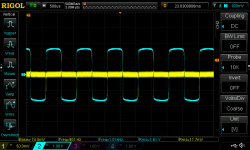
With music, you can see it "bounce" a little bit between what I'd estimate to be about +.25V and -.25V offset.
I captured it in the attached screenshot (blue trace is the output before C2 cap, yellow is after).
Nonetheless, meter is functioning great. Looking forward to soldering together a dual-channel version of the circuit with pots in place of R2 and R3 for eventual installation in the amplifier.
It stays perfectly stable after it settles post power-on with a sine wave fed into the input.
With music, you can see it "bounce" a little bit between what I'd estimate to be about +.25V and -.25V offset.
I captured it in the attached screenshot (blue trace is the output before C2 cap, yellow is after).
Nonetheless, meter is functioning great. Looking forward to soldering together a dual-channel version of the circuit with pots in place of R2 and R3 for eventual installation in the amplifier.
Attachments
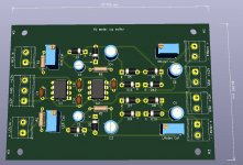
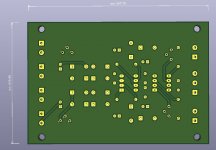
Yes! I ended up making a PCB for this circuit and it's currently running the two meters in the front panel of my amp. It needs a +/- ~12V supply. Happy to share details or gerbers when I'm back at home (currently traveling) if you're interested.
That is very generous of you.
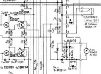
I also have a paper copy of the Yamaha MX-2000 service manual. A digital copy (not as clear as the original paper copy) is also online for free. That could be an interesting design to study as well, since it's a very, very fast and responsive meter driver.
I also have a paper copy of the Yamaha MX-2000 service manual. A digital copy (not as clear as the original paper copy) is also online for free. That could be an interesting design to study as well, since it's a very, very fast and responsive meter driver.
- Home
- Design & Build
- Parts
- VU meter and buffer circuit for amp - compressing readings logarithmically