Spent a while watching Utube npn/pnp and Mosfet testing 'quick 'n dirty' methods.
Sadly ..I suppose , ALL Mosfets and Transistors, Both PCB's ,test as OK and all are reading Decently close to each other.
No shorting in any way as described in videos.
No joy there.
Frankly It all seems OK.. So back to the darned thing Shorting to case/heatsink, theory.
Yet I can detect Nothing with continuity testings.
Mebe !? My DIY Kapton tape / Mica isolation leaves substitute could be the problem? No idea how as it seems a decent dielectric.
Wouldn't be the first time that one of my clever notions bit me though.
Will go to the local Junk Parts Emporium on Monday and buy 'real' (albeit Chinese imitation) Isolation leaves ..dunno their real name)
Might help .. might not. Not many other theories available at the moment.
Even my 'inexpensive' SMPS gizmos are working as advertised , I think? both outputting exactly 26 v on their respective rails.
Will definitely post any advancements..
Thank you all for efforts on my behalf.. Nice to get help.... it's appreciated (essential actually 😱.
Last edited:
The last thing I can think of is to test all the diodes themselves to make sure non of them are shorted. There has to be some reason why you are measuring a short.
On the positive side, we know the circuit works as drawn. Several of us have built them.
On the positive side, we know the circuit works as drawn. Several of us have built them.
Clearly I've managed Some bungle, it's a fairly straightforward PCB/build
I have a measured Short? Only between the Power spades do I have continuity.. on both boards. Dunno IF this is Good or Bad.
Could you please Meter Your VSSA? I need to know if there is intended to be Continuity between any /all combinations of the +, - , and ground spades on the PCB's
Will.. check all diodes.. it's easy enough.
Getting Ambiguous results on diodes. Sometimes good, sometimes not. What is a/the part # for the diodes? My Bom is MIA
Do bits (not just diodes but transistors as well ) need to be removed for reasonable readings/diagnosis ?
Do bits (not just diodes but transistors as well ) need to be removed for reasonable readings/diagnosis ?
Great! thank you.
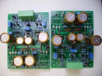
Diodes I fitted are 1N4007.
Q7 & Q9 are mounted with their wee upper left hand corner indent/dots facing the Heatsink.
Attaching a High Res PCB photo. [pesky Forum reduced the Res.. a lot. I can Email the real version?]
Perhaps helpful to the boards' father 😉
in identifying parts in wrong places/wrong values?
Oddly, in checking my flamed resistors I found that the flamed one on the + rail reads 104 Ohms, while the merely charred one on the - rail now reads at 9 ohms
Both were 11prior to cremation. Relevant?
Attachments
Last edited:
When you say you have continuity between power pins and ground in various combinations are you leaving the meter on long enough to ensure you aren't just charging up the on-board capacitance? That could give a false indication of continuity if your test is very quick.
It is entirely possible that due to the use of an SMPS that the resistors couldn't take the large current pulse that comes with how fast the PSU can apply the full rail voltage. If you have them, try something close to 10R in a higher wattage, say 3W or greater. There is the possibility that there is nothing wrong and the small resistors you used just couldn't hack it. I don't see anything obviously amiss.
It is entirely possible that due to the use of an SMPS that the resistors couldn't take the large current pulse that comes with how fast the PSU can apply the full rail voltage. If you have them, try something close to 10R in a higher wattage, say 3W or greater. There is the possibility that there is nothing wrong and the small resistors you used just couldn't hack it. I don't see anything obviously amiss.
I never really thought about it. I have never tried to use an SMPS for testing a new circuit. I always use a light bulb and a variac. I wonder if you can insert light bulbs in between the SMPS and the amp. That may work as a current limiter in case there is a short.
Hey! Great Minds?? Was just having that selfsame thought..
That the Silly SMPS was simply melting the Resistors with inrush.
Unfortunately I don't have an alternate available Power Source.
Do have 15V rails on the smps. Also have 11+Volts Lipo batteries and a spare 12v Moto battery... Those though could equal an SMPS in inrush though.
A couple of 12v Smps laptop types too?
Continuity? As in My Older silly Circuitest Meter has a Beeper/tone that Ignites with Continuity.
While My Cheapo but far more recent mfg Circuit test (looks Like the Crappy Harbourfreight Pink one) Has a more sophisticated reading on Diode mode
On it's testings of any and all, regardless of combinations, Power inputs And Spkr outs..the PCB 'Spades', the readouts keep increasing as the Caps seemingly are charging.
Oddly (reassuringly?) both boards do similar.
Suggesting that IF an Error it's Consistent
Still4given: I remember that You have the Same SMPS contraption.
What issues (if Any) did you encounter with using the thing.. realising that you didn't use it for initial setup?
Umm No Higher wattage available/on hand. Till Tomorrow when the Junk Shop opens..paralleled ones Might work?
Last edited:
That SMPS will shut down if there is a short. I will not continue to output 25v. Why not just hook it up and be ready to pull the plug if you hear it cycling on and off. If you are sure you have the mosfets in the right place there is likely no damage to occur.
Thanks.. Likely you are right.
But I needs screw up some courage First.. right after I reassemble the thing and fit 3W 10 ohm resistors.
Mosfets Are correctly located... I looked 🙂
Had No idea that I could/would hear the SMPS thing cycle. It seems as noiseless... so far.
Silly Me... I have a habit of trying slightly off the mainstream ideas/gizmos and often suffer the resultant setbacks.
Could be a lesson in that? Nawww.
One other thing to verify... Ensure you have the bias trim pot set to MAXIMUM resistance, if you have it set to the minimum you will have the bias circuit cut-off and the outputs will be biased into very heavy conduction. As I noted in the set-up procedure the design doesn't have padding resistors and as such isn't fool-proof with respect to trimmer settings.
Got it .. turned that thing until it faintly clicked at the end of it's travel 4850 ohms Triple checked to ensure I didn't damage it process.
Will have to reset Vr 1 , 3 as I set 270 ohms at the resistor Not at Q3 , Q6
It is all Sooo easy... when you've done it Before 😉
Will have to reset Vr 1 , 3 as I set 270 ohms at the resistor Not at Q3 , Q6
It is all Sooo easy... when you've done it Before 😉
interesting..
With 3w /10 ohmers.. as the Junque Shop had no such thing 🙄 Paralleled 3 30 ohm 1 watters.
Plugged into the SMPS .. they got Hot with the first tendrils of smoke...instantly! Turned it off immediately.
It all tested OK. afterwards.. so no damages at least
Tried the Other SMPS (was a dual setup)
Turns out ONE of the Chinese JUNK SMPS is the problem.
Oddly it Meters the correct(ish) 26v output ..... grr.
GO China!.. a Clear Lesson Learned.
Metered, the Inputs, where the SMPS connects to the Test 10 0hmers I get 23+ volts/rail.
This due to the resistors or the Garbage (but at least still working) PS ...Under- performing ?? it's claimed at 28 v output .. as If 🙄
Dubious as to whether this single SMPS can power Both PCB's adequately.
OR if the excreable thing won't self destruct and ruin them?
Sooo.... Seems I need a Reasonable PS..
Any boards? or directions to a Decent yet affordable one 😉
No Fresh Amp tunes to night.
Last edited:
I could send you a capacitance multiplier PSU board that should be good for a stereo set. You would need to source a suitable transformer and parts to stuff said boards. I'm 'in the field' at the moment so no links or references handy but you should be able to find my thread on it.
Hi,
I think this what you are referring to.
http://www.diyaudio.com/forums/powe...l-pmi-capacitance-multiplier.html#post3605532
Regards,
Berty
I think this what you are referring to.
http://www.diyaudio.com/forums/powe...l-pmi-capacitance-multiplier.html#post3605532
Regards,
Berty
Thanks Bertrand, that's the one. Go to post #65 if I recall correctly to see what I'm talking about.
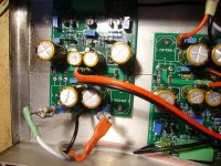
At the risk of stating the obvious, and wanting to ensure absolute clarity, you are placing the 10R resistors in series with the power supply lines and not in parallel, correct? As below:
PSU +V --> 10R --> AMP +V
PSU GND -------------> AMP GND
PSU -V --> 10R --> AMP -V
PSU +V --> 10R --> AMP +V
PSU GND -------------> AMP GND
PSU -V --> 10R --> AMP -V
Oooh No.. did You mean like this? 😉
Did All the adjustments/ trimmer fiddlings this afternoon.
Not comprehending: "insert an ammeter into the +V supply to measure total module current draw" Erm..Where to place Ammeter probes for this??
I used the Voltage method:
Across R13 I set 145mV Good Enuff?
00.2 mV DC offset
Takes a while to drop to that level offset and stabilise though. Wierd SMPS artifact .. Dunno?
But it does.. finally after ~5mins or so
As soon as I cobble up a Y connector to use my functioning SMPS I'll try to get this thing to Make sounds.
Still interested in your PS though 🙂
Read the thread about it. What V is it producing ? 24 V seems a good number 20 /25 W is Plenty with my speakers as long as there is enough backbone to manhandle the big Heavy LF cones.
Attachments
The resistors are more of a safeguard for the first power-up than anything else. In the absence of an ammeter you could read the voltage drop over one of those temporary resistors to indirectly measure total current.
One you have a module working with the resistors as you show, you remove the temporary 10R resistors. Replace one resistor with your ammeter and connect the other power connector directly to the module. That way you can read total current draw and set the output stage idling current using VR2. The module total current draw should be between 120mA and 160mA. Your ammeter should have ideally a 200mA range or alternatively a 2A range for this adjustment.
PSU +V --> AMMETER --> AMP +V
PSU GND -----------------> AMP GND
PSU -V -------------------> AMP -V
The measurement across R13 can be anywhere from 120mV to 160mV and tells you what the current through the VAS (the smaller transistors touching the heat sink) is. It takes a bit for thermal equilibrium to occur, so things can wander about just a little but that is nothing to worry about.
The PSU I pointed you towards can be flexible about output, it just depends on the secondary voltage you feed it. It will drop about 2V from the bulk side to the filtered side, so if your target was 24V output you'd choose a transformer that would give 26-28V (18-20VAC secondary voltage) after rectification.
Sounds like progress is being made 😀.
- Status
- Not open for further replies.
- Home
- Amplifiers
- Solid State
- VSSA Through-Hole Version by Jason