Dear Bangla,
I see that the input cable's shield's go to star point? And also to the board? If so - thats wrong. They should connect at one point, and then go to star gnd point. Board's signal gnd also should connect to the only point - star gnd. Power gnd (on board) traces schould connect to star point with separate wires.
Also as mentioned before rails wires should be twisted.
Hallo Guitar.mod.
Thank you for looking and advice.
I don't forget what is wrote by Andrew to twist wire.
It is in mind to do, but i need reorder some material to rework on this.
Regards Bangla.
Thank you for looking and advice.
I don't forget what is wrote by Andrew to twist wire.
It is in mind to do, but i need reorder some material to rework on this.
Regards Bangla.
Those input caps are hanging out are like big noise antennas too. Something mounted directly to the board might help.
Hallo jwilhelm.Those input caps are hanging out are like big noise antennas too.
That comes not in my mind, thank you for advice.
The vssa seems to be more sensitive to make failure.
I have used "antenna" style to test different input caps, but that combination Nichicon QXP and add a russian PIO works fine for me, so i have to solder in on place.
At moment all works without (marginally right channel) hum.
I will work to eliminate points.
I was actual reading about Valerys ideas " Revisiting some "old" ideas from 1970's IPS OPS", where you involved. Very interesting. The (your) Vertical CFA + NS- OPS awesome, but bad for my eyes- SMT Parts.
Valery sells me Ampliwire Boards wich now received to me. I will fit it to Baby Slew.
Regards Bangla.
Hi thimios,
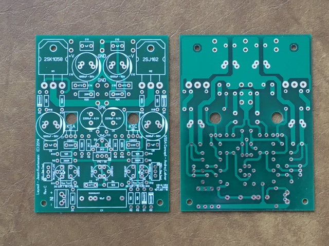
The posted gerbers are for the revision 'B' boards. There is a revision 'C' which is electrically identical with just a few minor trace routing and silk updates. If you are interested I can put up the files.
I'm interested, can you post boards revision 'C'? Gerber and Excellon or PDF.
With ALL accolades to Jason who was Courteous friendly and very Helpfull.
Kudos Mate!
I Subsequently built an F6..... which in truth... made MY VSSA sound like a transistor radio. Massive differences.
You WILL however have to use genuinely decent Speakers (No! Mark Audio et al Full ranger cheap *** drivers... those are Not up to it 😉 to gain full benefits.
Pay now, pay later..there's NO free lunch.. Kids
Last edited:
You must have done something wrong building your VSSA. There is nothing missing in the sound stage if done properly.
You must have done something wrong building your VSSA. There is nothing missing in the sound stage if done properly.
+1
It's singing now
Progress...
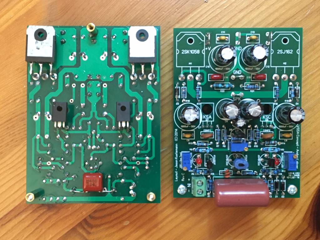
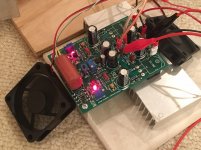
Test setup to adjust VAS current - cant get any lower than 280mV (140mV desired). I think it may be because I ran out of room since I am using 500R pots which were called for in the non-LED version. Nonetheless, it is singing now, albeit at a hot bias, 10R safety resistors still in place. Sounds quite nice. Circuit probably is good with exception of my incorrect VR1 and VR3. Is there a resistor I can change that will allow me to use the 500R's as I am all out of 1k pots?

These Aliexpress lateral FETs (labeled Hitachi) appear to be working.
Progress...
Test setup to adjust VAS current - cant get any lower than 280mV (140mV desired). I think it may be because I ran out of room since I am using 500R pots which were called for in the non-LED version. Nonetheless, it is singing now, albeit at a hot bias, 10R safety resistors still in place. Sounds quite nice. Circuit probably is good with exception of my incorrect VR1 and VR3. Is there a resistor I can change that will allow me to use the 500R's as I am all out of 1k pots?
These Aliexpress lateral FETs (labeled Hitachi) appear to be working.
Attachments

Lateral mosFETs have the Source pin in the middle of the plastic packaged versions.
I take it you have confirmed your Hitachi labelled devices match that?
The Vbe multiplier works on resistor ratios to determine the bias voltage.
The multiplier is actually a shunt voltage regulator.
You can calculate the resistor ratios and use that to determine the regulator output voltage.
I take it you have confirmed your Hitachi labelled devices match that?
The Vbe multiplier works on resistor ratios to determine the bias voltage.
The multiplier is actually a shunt voltage regulator.
You can calculate the resistor ratios and use that to determine the regulator output voltage.
Unfortunately, you will have to use 1k potentiometers to have appropriate adjustment range. There were no additional series resistors in this layout to make possible the use of the 500R unit you installed.
Lateral mosFETs have the Source pin in the middle of the plastic packaged versions.
I take it you have confirmed your Hitachi labelled devices match that?
The Vbe multiplier works on resistor ratios to determine the bias voltage.
The multiplier is actually a shunt voltage regulator.
You can calculate the resistor ratios and use that to determine the regulator output voltage.
If the unit works at all then the pin-out will be correct, otherwise the body diodes would be shorting the supplies.
It isn't the VBE multiplier he is referencing, he used the wrong value trimmer in the CCSs and therefore does not have appropriate range of adjustment. If the CCSs are running 'hot' so will the VAS current. The output current is controlled by the VBE multiplier and is mostly independent in adjustment.
Last edited:
You must have done something wrong building your VSSA. There is nothing missing in the sound stage if done properly.
I agree. This amp sounds great. I just noticed a slight flatness at very low output levels, which is common in a lot of amplifiers.
Unfortunately, you will have to use 1k potentiometers to have appropriate adjustment range. There were no additional series resistors in this layout to make possible the use of the 500R unit you installed.
I could pop out the LEDs and put in transistors until the new pots come in. That would also require changing a resistor value. It's so much more cool with lights though.
Lateral mosFETs have the Source pin in the middle of the plastic packaged versions.
I take it you have confirmed your Hitachi labelled devices match that?
The Vbe multiplier works on resistor ratios to determine the bias voltage.
The multiplier is actually a shunt voltage regulator.
You can calculate the resistor ratios and use that to determine the regulator output voltage.
Ha ha, I never bothered to "check". The amp fired up and responded to trim pots without hitting the rails. That's my first sign of good news. Then it plays music and can play loud without going poof in a puff of magic smoke. So that's the other sign it works. Frankly, I was prepared for these being fakes as the case looks old - the Pb solder coating on the pins looks oxidized. The epoxy case was not clean but the Hitachi symbol was there and not something I had seen before as others I have are Renesas. This might actually be a real Hitachi from old stock. The pins are almost oval in profile vs flat cut pins. Don't know - but plays music. 🙂
I agree. This amp sounds great. I just noticed a slight flatness at very low output levels, which is common in a lot of amplifiers.
It would be interesting to know it that is the amp or the speakers that are flattening out at low volume. It could even be the listening environment. There are a lot of factors that go into what we think we hear.
It would be interesting to know it that is the amp or the speakers that are flattening out at low volume. It could even be the listening environment. There are a lot of factors that go into what we think we hear.
I have not had a chance to get a proper listen to the VSSA yet until I fix my incorrect pot issue. However, I can comment on perhaps a general observation of my own amps that use the 2SK/2SJ lateral FETs vs ones that use the IRFP vertical FETs. My vertical FET amps seem to be more dynamic, and more powerful sounding bass, even at lower volumes relative to the lateral FET ones. It may be that the music is more accurately portrayed with the lateral FETs, but the verticals seem to give it more authority. This has been my experience with a limited sample of: FX8, FX8 Bimo vs FH9, FH9HV, VHEX+.
The VSSA is a current feedback amp, so maybe it will be totally different and blow me away when I get to properly listen to it?
Most Vertical mosFETs of similar power to Lateral ,osFETs have much higher gm.
That higher gm will give more response to a voltage change at the gate.
I think that would be measurable and maybe audible.
The low gm of lateral mosFETs is probably why Laterals seem to benefit from fitting extra pairs compared to Verticals.
I would automatically fit 2 pr Laterals to any power amplifier just to get the gm up to more normal levels.
Output current is the audio we get from our speakers.
gm is a measure of output current change for a fixed level of gate voltage change.
- Status
- Not open for further replies.
- Home
- Amplifiers
- Solid State
- VSSA Through-Hole Version by Jason