I think I have decided that the next iteration will use LED biased BJT CCSs. The JFET option is simple but based on some reading I don't think it offers any real benefit and with continually declining availability in JFETs I'm less inclined to pursue it. LEDs give some indication the circuit is operational and look pretty 😀.
There will always be opinions on this, but the CCSs are really serving to stabilize the operating point of the circuit and in my opinion don't really do too much for the sound, either good or bad. The design sounds fine biased with resistors, a la the PeeCeeBee, but is easier for a builder to get it operating well with the CCSs.
There will always be opinions on this, but the CCSs are really serving to stabilize the operating point of the circuit and in my opinion don't really do too much for the sound, either good or bad. The design sounds fine biased with resistors, a la the PeeCeeBee, but is easier for a builder to get it operating well with the CCSs.
I see, maybe I will try the led+bjt ccs once I'm done with Jfet ccs and compare them by listening test! 😀
By the way have you tried a prototype with the led+bjt ccs?
By the way have you tried a prototype with the led+bjt ccs?
I've tried both the 2Q and the 1Q+LED. My 'permanent' builds were configured with the 2Q for no particular reason other than the boards were developed around that option. I don't feel there was any real difference between their sonics. There has been at least one other that used the LED biasing for the CCS, member Sheldon IIRC.
Hi Jason...
I'm beginning populating my boards from you (4pcs. Rev C)...with regards to LED...what particular LED you use...are these ordinary or high brightness type? I plan to use blue LED which i have..is there any limitation on this..
The Vbe multiplier is on board and not on the heatsink for better thermal tracking. Is this not necessary since we use lateral Mosfet?
C1 size is a little big for my available 10uF...can I use lower value say 2.2uf which will fit in?
Last thing, Vr1 and Vr3 are variable and some has 220 ohm resistor....this vr1 vr3 really needed or can we just use matched 220 resistors?
Hi Junm,
The LEDs ar supposed to be 'regular' red, not high efficiency. Blue LEDs are not quite as quiet as the red ones and have about double the forward voltage. I don't suggest using blue, but if you do there are two caveats:
1) VR1 and VR3 will have to be changed in value to 2K units and pre-set to somewhere in the 1K to 1K2 range and adjusted from there
2) Using 2K units for VR1 and VR2 will make the adjustment touchy
The Vbe is deliberately separate from the heat sink. With 100mA+ of current through the outputs we get near zero temperature co-efficient and don't need thermal tracking. I went with a Vbe to be free from variances in component tolerances and parts that might be harder to find word-wide.
C1 has multiple pin pitch options for the input capacitor and a fairly large available footprint, so you should be able to get a 10uF that will fit. Use a non-polar electrolytic if you have to. I suggest not going any lower than 4u7 on the input capacitor.
VR1 and VR3 have always been 500R potentiometers, you may have seen the value arrived at in simulation. In real-life the required value is nearer 270R, and to allow for the VAS current and DC offset to be adjusted they should be variable. If you really need to minimize the number of variable resistors, then put a 270R in place of VR3 and put a 500R VR into VR1 so you can still adjust offset. Due to component tolerances you likely won't get a satisfactory set-up using fixed resistors.
Hi Junm,
The LEDs ar supposed to be 'regular' red, not high efficiency. Blue LEDs are not quite as quiet as the red ones and have about double the forward voltage.
The standard (not high efficiency) red LED is the best choice, also, because it has a lowest, most linear impedance. And the current is within its linear region.
Sheldon
Thanks Jason and sheldon....okay I have several regular red LED to use....Now I can procced in the system completion...
Hi Jason,
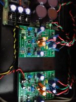
I have successfully completed the vssa rev C boards supplied by you for a stereo application. Thank you for the PCB and your support. soldering was fun and easy perfect LS for all components. Only VAS trannies were a bit crtical to mount. Sounds amazing. Didn't need much adjusting at all. Here is the set up .
1. Trafo-300VA 24VAC
2. Bulk PSU - +/-34 VDC (no load) with 40kuF.
3. VAS current (Voltage across R13/14)- Approx 160-162VDC on both channels
4. DC offset-0.1mV (yes ! I measured it many times , DMM shows 0.1mV on 200mV scale.)
Individually both channels were tested with MP3 player and there was no start up pop/ hum of any kind. **Didnt understand why VR2 -5k pot is needed at all**.
However when I put both channels in a chassis with a dual gang pot for volume control, there is audible hum with both sources(MP3 player and CD player). checked everything and no clues. I have connected the PSU ground ( audio ground) directly to chassis earth (although they connect to chassis at different points).
Another issue is that , even when the pot is fully turned for muting, there is sound coming from both channels.
Out of solutions here, help please!
reg
Prasi
Attachments

I think you combined both channels in stereo setup as power amps (no volume control ?) with just 1 power supply ? If so then please show how GND of both channels inputs is connected and how the safety grounding has been connected to GND.
* Why did you use different input caps for each channel ? That is a thing you can hear and it is not logic to do that. I see a few differences between channels, in a stereo setup it is common practice to keep both channels identical. Differences between both amps can spoil the fun.
* Why did you use different input caps for each channel ? That is a thing you can hear and it is not logic to do that. I see a few differences between channels, in a stereo setup it is common practice to keep both channels identical. Differences between both amps can spoil the fun.
Last edited:
I think you combined both channels in stereo setup as power amps (no volume control ?) with just 1 power supply ? If so then please show how GND of both channels inputs is connected and how the safety grounding has been connected to GND.
* Why did you use different input caps for each channel ? That is a thing you can hear and it is not logic to do that. I see a few differences between channels, in a stereo setup it is common practice to keep both channels identical. Differences between both amps can spoil the fun.
Hello Mr. Jean Paul,
thank you for the reply. Here are the answers
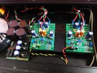
1. Yes , it a stereo amp with 1 amp for each channel, 1 common trafo, 1 common PSU.
2.the pdf attachment shows the gnding connections. PSU has a star grounding
3. the amps internal grounding is shown in the attached image by Jkuetemann.
4. i/p cap: I used what I had in hand. (both are 10uF 50V NP caps although different manufacturers)
5. Only difference between two channels is the i/p cap and signal ground seperating diodes (1N914's on one channel and 1n4007 on the other) and i/p connector.
reg
prasi
Attachments
Dear Prasi,
try to connect speaker GND return wires to Common GND on the PSU.
Also it is recommended chassis ground to connect near input - RCA gnd. Also maybe The RCA jacks are not isolated properly from chasis and now there are two connections to Chasis - not recommended. Should be only one.
try to connect speaker GND return wires to Common GND on the PSU.
Also it is recommended chassis ground to connect near input - RCA gnd. Also maybe The RCA jacks are not isolated properly from chasis and now there are two connections to Chasis - not recommended. Should be only one.
Dear Prasi,
try to connect speaker GND return wires to Common GND on the PSU.
Also it is recommended chassis ground to connect near input - RCA gnd. Also maybe The RCA jacks are not isolated properly from chasis and now there are two connections to Chasis - not recommended. Should be only one.
Dear Guitar.mod,
as per your suggestion, Just now connected the spk returns to PSU ground, but hum still present (same amplitude).
RCA's are insulated ones and mounted on back panel which is acrylic.
just checked one more thing.
when signal ground is directly connected to chassis ground by a separate wire , the hum decreased noticeably. now the hum is inaudible from may be more than 1 m away.
Does that tell you guys something? is this the solution or should I try something else like a disconnecting network? (bridge rectifier, cap and resistor)
reg
Prasi
Last edited:
when signal ground is directly connected to chassis ground by a separate wire , the hum decreased noticeably. now the hum is inaudible from may be more than 1 m away.
Does that tell you guys something? is this the solution or should I try something else like a disconnecting network?
You Should disconnect existing ground wire from PSU to chassis, and connect one wire from input RCA gnd terminals to chassis. Only one point schould be connected to chassis GND from "audio gnd".
As the problem appears when You connected the Volume Pots and both amps -
also You could try leaving the main connection to chassis as is, but the grounds from inputs - connect directly to star ground point on PSU, similar like here:
http://mark.rehorst.com/LM3886_amp/LM3886_amp_schematic.png
also You could try leaving the main connection to chassis as is, but the grounds from inputs - connect directly to star ground point on PSU, similar like here:
http://mark.rehorst.com/LM3886_amp/LM3886_amp_schematic.png
It's easier to leave the chassis ground temporarily disconnected while sorting out the hum issues, the once the amp is silent, make one connection from the star ground to chassis ground.
Hi Jason,
I have successfully completed the vssa rev C boards supplied by you for a stereo application. Thank you for the PCB and your support. soldering was fun and easy perfect LS for all components. Only VAS trannies were a bit crtical to mount. Sounds amazing. Didn't need much adjusting at all. Here is the set up .
1. Trafo-300VA 24VAC
2. Bulk PSU - +/-34 VDC (no load) with 40kuF.
3. VAS current (Voltage across R13/14)- Approx 160-162VDC on both channels
4. DC offset-0.1mV (yes ! I measured it many times , DMM shows 0.1mV on 200mV scale.)
Individually both channels were tested with MP3 player and there was no start up pop/ hum of any kind. **Didnt understand why VR2 -5k pot is needed at all**.
However when I put both channels in a chassis with a dual gang pot for volume control, there is audible hum with both sources(MP3 player and CD player). checked everything and no clues. I have connected the PSU ground ( audio ground) directly to chassis earth (although they connect to chassis at different points).
Another issue is that , even when the pot is fully turned for muting, there is sound coming from both channels.
Out of solutions here, help please!
reg
Prasi
Hi Prasi,
Thanks for the feedback. Based on what you say, here's a few things to try.
There should only be one physical connection to the chassis. Using the chassis as a conductor by having two physical connections in different places can cause a loop.
You can sometimes get better performance by shorting the input ground loop breaker (the 10R and parallel anti-polarity diodes). Alternatively, try dedicated ground connections from the input connector to main ground point.
Your volume pot may have a high impedance wiper contact to the element and it may also not track well, hence the inability to get full muting. Try a different pot, say a 20K audio pot or fake it with a 100K linear + 11K fixed resistor (wiper to common).
Ensure you have isolation of the input connectors.
Isolate the volume pot body and run a dedicated ground from the pot body to the main ground.
In any event you have a ground issue or a really bad volume pot.
**The 5K pot is for bias adjustment of the output devices. Total current flow to each channel should be adjusted to be about 120mA or so, a little higher higher if there's good heat sink, up to about 180mA maximum***
I jumpered the 10R ground lift resistor, and now the hum is only audible if i put my ears to speakers (2.5" full range-test speakers, ~90dB ) and not audible from ~10cm away. It is slightly volume dependent. (i.e. with no music is playing, when i increase the volume to max , the hum increases ever so slightly, but is still inaudible from 10cm away.) I left the anti-parallel diodes in place as they shouldn't now be affecting the circuit in anyway (your thoughts please?). running a wire from pot body to main ground made no difference
should I consider that the hum problem is solved?
Also wire from earth pin and wire from audio ground from PSU now connect at the same point on chassis (this didnt make any difference).
Volume pot:
1. the volume pot i used is 16mm alpha 10k dual gang log pot. I had used it previously on my APEX LM3886 and it worked quite well. when at minimum position, the resistance (common to wiper) measured about 1.5ohms, is this the problem?
2. tried 100k pot with 12k resistors from common to wiper, still can hear music at min position.
3. pot and RCA's are isolated from chassis (acrylic front and back panels).
** I didnt adjust bias (current across 10r inline resistors). the heat sink is at ambient temp even after half an hour. Should I leave it as it is or adjust the bias? VAS current is also stable at 161mV on one channel and 159mV on the other. DC offset is still 0.1mV. Zobel resistor is super cool. There is no distortion of any kind and sounds lovely even with crappy speakers.
tonight I will put the amp on my main speakers and will share the impressions.
Last edited:
Just checked bias, it was 0.72VDC across inline 10R. when i tried adjusting it, it is insensitive initially and suddenly jumps to 2VDC. I set it at 1.2V but its slowly varying from 0.85V to 1.6V even after leaving it on for half an hour. any problems?
Hi Jason,
finally was able to adjust the bias, @ 1.21-1.25VDC on both channels -stable for half hour. I think the bias pot is to be blamed here (chinese bourns-resistance itself was jumping around, will change it later).. second channel was much easier and was done in 5 mins(it is the one you supplied with all pots and small resistors).
Sound impressions,
been listening to it for the past hour on my main floor-standers and its Simply amazing. singer is dead center, details amazing. sound stage is superb. instruments never sounded so good. very accurate bass. this amp truely revealed the quality of my diy speakers. very pleased with self 😉.
All credit goes to Jason for the design and layout and sending PCBs (of course LC) and Jeff for sending me critical components.
I think most people would not want to listen to anything else if they listen this amp. totally shames LM3886. my other commercial solid state has too much pronounced bass (VFA🙄) and suffers in high end.
reg
prasi
If you can't hear any hum from closer than you would care to sit then I personally consider it a non-problem.
The bias is not thermally compensated because the lateral MOSFETs are supposed to be close to a zero tempco in the neighborhood of >100mA and <200mA, but in reality it will wander some. If needed it will sound fine set to a lower bias current. VAS is fine anywhere from 12mA to 16mA, I usually shoot for 14mA and it will stay in the ideal range.
I'm really not sure why you aren't getting full muting when the volume pot is at minimum. Could your input wiring be picking up signal from somewhere? How loud are we talking about?
- Status
- Not open for further replies.
- Home
- Amplifiers
- Solid State
- VSSA Through-Hole Version by Jason