No PCB sales. I made mine using Sprint Layout 6 and Kinsten pre-sensitized board. If you refer to earlier posts by Jason and others in this thread, I am sure there will be suitable board designs that you can use.
I am happy to share my SL6 design file but I don't want to hijack this thread so perhaps the above is the best option. The moderator can decide.
I am happy to share my SL6 design file but I don't want to hijack this thread so perhaps the above is the best option. The moderator can decide.
I don't say for pcb sales but for pcb design that would be share.🙂No PCB sales. I made mine using Sprint Layout 6 and Kinsten pre-sensitized board. If you refer to earlier posts by Jason and others in this thread, I am sure there will be suitable board designs that you can use.
I am happy to share my SL6 design file but I don't want to hijack this thread so perhaps the above is the best option. The moderator can decide.
Re: Sprint Layout file
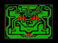
Please find attached the uploaded SL6 file. Note that the orientation of the 1000 uF cap located closest to the negative power connector has been rotated 180 degrees to correct its polarity.
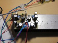
I have built this board, populated it and expect to run through its set-up and tests over the next few days.

Please find attached the uploaded SL6 file. Note that the orientation of the 1000 uF cap located closest to the negative power connector has been rotated 180 degrees to correct its polarity.
I have built this board, populated it and expect to run through its set-up and tests over the next few days.
Attachments
VSSA with CM running
Thimios,
I have set up and run the modified VSSA amp with the cap multiplier. It has to be the easiest amp to set up ever! Offset voltage was 2mV cold and around 6 mV warm with no additional adjustment. I will adjust to reduce the warmed up offset voltage later. Also I used 145mV across the two 10R VAS resistors and that voltage remained stable when warmed up.
Audio quality seems good but I will have to hook up decent speakers and a better source to truly compare with my other amps.
I found a minor error in my PCB input circuit layout which I have corrected in the attached SL6 file.
I will now build the second channel and hopefully it will be just as easy.
Attachments
Dear TCD1963,
Kindly also post the exact circuit used.
gannaji
I believe it already has been posted, located just a few posts back >HERE<
Boosted rails
Hi Jason,
Have you looked at the effect of using higher voltage rails for the input and VAS? Are the suggested improvements audible? Worth the extra design hassles?
Hi Jason,
Have you looked at the effect of using higher voltage rails for the input and VAS? Are the suggested improvements audible? Worth the extra design hassles?
Hi Jason,
Have you looked at the effect of using higher voltage rails for the input and VAS? Are the suggested improvements audible? Worth the extra design hassles?
I personally doubt getting a few volts more swing out will make much difference. If one needs a bigger amplifier then one should build a different design. The VSSA, as generally presented, tops out at about +/-45V supplies. Of course, with the CM already on board you only need to make feeding the CM from an alternative supply possible. The added complexity is really part of the supply at that point.
As mentioned before, I pondered the integrated CM previously but decided to abandon that line of thinking. The next logical step led to boosted rails for the front end and things were getting messy. I wanted to keep things relatively simple. I did make a few different choices than the original, but more to broaden appeal than anything else.
Hi Jason,
Why did you remove the 10uF film bypass for the 2200uF caps?
I see the 2k2 resistors are now 1W. Do they need to be? It's not so easy to find a 0.1% 1W resistor for that role. From previous threads I read it's recommended these resitors to be matched as close as possible.
Why did you remove the 10uF film bypass for the 2200uF caps?
I see the 2k2 resistors are now 1W. Do they need to be? It's not so easy to find a 0.1% 1W resistor for that role. From previous threads I read it's recommended these resitors to be matched as close as possible.
Hi Paulo,
I have never included the film bypasses. I just didn't feel they really made a difference (yes I have tried with and without) and they seriously compromised my earlier layouts.
The 1W feedback network is to just keep them stone cold under all conditions. They do not NEED to be that big. They also are fine if you select from a small sample, say 10 to 20 pieces, of 1% devices.
Does a Nichicon Fine Gold 2200uF fits? It's a little latger than others 2200uF.
I like your design, the board is looking very very good!
I like your design, the board is looking very very good!
A quick off-topic for which I apologize in advance:
Will too hot VAS transistors result in 2nd harmonic distortion? i'm finding my VSSA a bit too "sweet" sounding... Like a high distortion tube amp, a bit artificial sounding. Could it be the VAS?
Will too hot VAS transistors result in 2nd harmonic distortion? i'm finding my VSSA a bit too "sweet" sounding... Like a high distortion tube amp, a bit artificial sounding. Could it be the VAS?
How much current is flowing through VAS transistors?A quick off-topic for which I apologize in advance:
Will too hot VAS transistors result in 2nd harmonic distortion? i'm finding my VSSA a bit too "sweet" sounding... Like a high distortion tube amp, a bit artificial sounding. Could it be the VAS?
p.s. Second harmonic distortion happens when one half of signal (i.e. testing with sinewave) is not symetrical to other half.
About 13mA at start up and going higher to about 16mA when hot. Could it also be a hfe missmatch?
Do you have mixed grades of devices for the VAS? Like KSC3503D and KSA1381E? I have used them without any real issues, though with a 2:1 difference in hFE that would increase the H2 somewhat.
Are you using 22pF for compensation?
Bring a few more adjectives to the description. When you say 'sweet' are you suggesting a little dull at the high end? You can try a 100pF in the input filter, replacing the 470pF, to increase the bandwidth to be way beyond the audio band.
Are you using 22pF for compensation?
Bring a few more adjectives to the description. When you say 'sweet' are you suggesting a little dull at the high end? You can try a 100pF in the input filter, replacing the 470pF, to increase the bandwidth to be way beyond the audio band.
I'm using KSC3503E and KSA1381E but I couldn't match them, they are about 50 hfe units apart from each other. I'm using 47pF compensation and 330pF as input filter.
It's difficult for me to put in to words the sound I'm perceiving. I lack all the audiophile jargon. I notice this effect more in female voices, it's nice and mellow sound but too much of it. Maybe the high end it's a bit recessed and the mid range takes the spotlight giving an artificial mellow sound.
It's difficult for me to put in to words the sound I'm perceiving. I lack all the audiophile jargon. I notice this effect more in female voices, it's nice and mellow sound but too much of it. Maybe the high end it's a bit recessed and the mid range takes the spotlight giving an artificial mellow sound.
To me it looks like 2nd harmonic distortion but I'm not sure. It reminds me a high distortion tube amp, very "mellow" and mid centric. The VAS transistors have small heatsinks and they became quite hot. That's why I much prefer to have them on the main heatsink.
Last edited:
High distortion and "mid centric" sound is in guitar amplifiers (i.e. Marshall). This sound is due high gain and limited bandwith. I don't believe VSSA could do that because of hot VAS transistors, or hfe mismach. This mismach is compensated with negative feedback loop resistors if whole circuit has enough gain. Second harmonic distortion also could be due not equal negative feedback loop resistors.To me it looks like 2nd harmonic distortion but I'm not sure. It reminds me a high distortion tube amp, very "mellow" and mid centric.
p.s. To leave too hot VAS transistors - also not good idea.
- Status
- Not open for further replies.
- Home
- Amplifiers
- Solid State
- VSSA Through-Hole Version by Jason