focal7C
As a trial try take ground for speakers at the PCB spade (more downstream) and see what happen.
As a trial try take ground for speakers at the PCB spade (more downstream) and see what happen.
I have always used the provided ground on the board for the speaker return, if you haven't tried that yet please do. You can also try running a set of ground wires from the input jacks to the chassis ground.
I was using one specific piece of equipment and had some buzz, but it turned out in my case to be what I was using for my pre. A different pre is dead silent. In any case there should be no noise when using an isolated source like an MP3 player.
I was using one specific piece of equipment and had some buzz, but it turned out in my case to be what I was using for my pre. A different pre is dead silent. In any case there should be no noise when using an isolated source like an MP3 player.
Are these tested as single channels without mounted in the enclosure?Has anybody else had ground loop problems with the VSSA or similar amp builds?
I'm getting a low tone buzzing sound that is just audible from 3 meters away.
Would really appreciate suggestions on further analysis or a fix.
Now have a star ground lift, RCAs checked so outer casing doesn't contact backplate and soldered a bypass on R3 but buzzing persists albeit not quite as loud.
Thought I had narrowed problem with an initial wire test bypass of R3 as I could get alternate channels quiet. But may have shortened the bypass wire with R2 / D1 or touched some other part...
These are the symptoms:
1. Most buzz with both RCAs plugged in
2. Very minor buzz with only right channel RCA plugged in (can hear from 50 cm)
3. Slight buzz with right channel RCA plugged into left channel
4. Bit louder buzz with left channel RCA plugged into left or right channel (can hear from 1 meter)
5. Also buzzing out of the speaker of channel not plugged in
6. Using a B1 preamp it generated more buzzing as well as a high pitch noise
7. Plugged preamp in to TPA3116D2 chipamp - No audible buzzing
8. Plugged in mobile phone instead of CDP to preamp - buzz remains
9. Preamp RCAs not plugged in - no buzzing
10. Created deliberate ground loop without preamp plugged in (tied RCA L/R in negatives together) - Same buzzing
11. Took ground of preamp circuit to VSSA lifted star ground - more buzzing sound than usual
12. Ground of preamp circuit to chassis of preamp - Same buzzing
13. Preamp circuit ground direct to mains earth - more buzzing than usual
14. Used extension chord to different house wall socket (on different fuse) - same buzzing
15. Ran a wire directly from the RCA ground lug to the star ground - status quo
Cheers, Roger
Each board has its grounds arranged to basically be a star of its own. It should only need its main ground tab connected back to the main physical star on the PSU. This will produce a star-on-star arrangement.
I would still like to see the speaker return on the amplified board utilized to see if that makes any difference.
I would still like to see the speaker return on the amplified board utilized to see if that makes any difference.
Thanks Dobrivoje, think I'm getting closer... Now only the left channel is buzzing (but less).
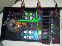
Took ground from after smoothing caps and connected to all other green wires + centre tap and return. See latest photos.
(Also tested using the GND speaker return on board to output or back to star point, but that didn't make any difference).
What's the best way of measuring for points on the left channel PCB that are not grounded or returns that are not properly connected?
Checked PSU ground solder joints. Left channel amp GND lug also looks solid.
Star connection is soldered and screwed together
Attachments
Last edited:
Roger, you still have ground loops. To avoid them you should have only five wires, like I drew them: one from center tap of transformer secondary, two from supply pcbs and two from speaker terminals. Nothing else. You should remove wires from input side of supply boards.
Although my English is poor, I hope I was clear.
Although my English is poor, I hope I was clear.
Ok Dobrivoje, Think I understand now. Nothing wrong with your English and illustration 🙂
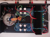
Have since cut both wires from the AC side of the PSU boards. There is now only four green wires going in to the star, plus the centre tap. Another wire goes out to the case via two diodes (half of the second rectifier is used) with a resistor and small ceramic between.
Results in buzz from both speakers again, however still quite soft and barely audible from about 1 meter.
If I temporarily reinsert the left PSU GDN the revolutions of the buzz increases slightly (but not the pitch).
Could it be a noisy transformer or rectifier as well?
focal7C suggest that to have better owerview that connect and run only right channel, work with it until perfect, then do same setup only for left channel and it should also be perfect now and if not some error exist. Then when both run perfect by their own run them both for stereo and take eventually new problems from there on.
EDIT: as thimios asked post 543 are these tested as single channels without mounted in the enclosure and out there they did run error free ?
EDIT: as thimios asked post 543 are these tested as single channels without mounted in the enclosure and out there they did run error free ?
Last edited:
Now power supply ground is wired properly. If you short signal inputs to ground, amp should be dead quiet. If not, try witout a star ground lift. You also can try to connect speaker returns to amp pcbs, like Jason suggested at post #545.
And, of course, try BYRTT's suggestion, channel by channel.
And, of course, try BYRTT's suggestion, channel by channel.
Last edited:
Roger, as long as you'll have some wire-distance between input GND and speaker GND, there will be buzz/hum. These both GND's should be one single reference point, if not feedback will always pick rectified AC current voltage drop on the wire between the two GND's, resulting in added modulation to the input signal. Also shorten 10 ohm GND isolationg resistor to get real zero buzz/hum.
Yes, shorting signal to ground results in amp being dead quiet
Without a ground lift - buzz
Only left channel VCC power connected - buzz
Only right channel VCC power connected - buzz
Speaker return L to PCB GND - higher rev buzz (since proper ground re-wiring)
Speaker return R to PCB GND - higher rev buzz (with power to other channel disconnected)
Speaker return L and R to PCB GNDs - higher rev buzz
So Lazy Cat, I need to listen from more than 1 meter away, get less sensitive speakers or wait a few years for my hearing to deteriorate 😉 Or are you suggesting I take the return ground to speaker out from the same point as the speaker ground connection on the PCB?
A friend says can hear some buzz from your version but he has to get right up close to the speaker in his setup.
Thank you Dobrivoje, definitely an improvement with proper power supply ground.
Running it in at the same time and it already has some characteristics which are better than my current favourite.
Last edited:
OK, you report that shorted inputs results in a quiet amplifier. Is the amplifier also quiet with open inputs (that is the inputs not connected to any other device)? If not then you still have some kind of ground loop / interference that is completely internal to your build. If it requires a source to be connected to get buzzing, then a loop is being formed with the source device. Did I read you correctly that a portable MP3 player gave a buzzing amplifier too? It shouldn't if we are talking about typical ground loop issues since such a source is completely isolated.
So, at this point I'd suggest testing the build using one PSU filter board just to eliminate the possibility they are allowing relatively large currents to flow between their grounds. I'm seeing one transformer and rectifier and two filter banks. Try it with just one.
Also, another thought, I had some really dubious 'shielded' cable that didn't work worth a crap at one point in time. Try some better cable or even just go to some very tightly twisted Cat5e pairs to feed the input to the amplifier.
It is no longer quiet with open inputs 🙁 Android device connected directly also buzzes but a bit differently. Thanks for your suggestions and will try a single PSU. Will the 4 x 4700 uF be sufficient or should I add a couple more capacitors? (Will probably have to be in a few days time before I can test this). Might try it with two separate rectifiers feeding each PSU as well.
Last edited:
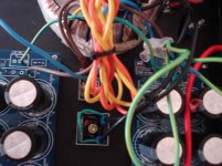
The red speaker out cable doesn't seem to be very good quality and is oversized. Re-routing away from PSU/caps might also be advisable.
Should probably put R3 back in as well and redo some of the tests.
Should probably put R3 back in as well and redo some of the tests.
Roger, it's everything OK with power supply and amplifier. Problem is at input signal side. Do what Jason suggests. VSSA has very wide bandwidth, so it may not be easy, but once you solve the problem, you'll be very satisfied with your amplifier.
Thought case was closed, seems very troublesome. Among what have been proposed already think you will nail it  (My take one would be for one channel i would try jkuetemann proposal of changing input cable), in meantime here some more checks maybe little silly 🙂.
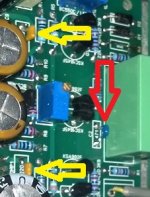
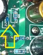
In attached picture by red arrow C2 BOM says 470pF could it by accident be 47-4,7pF and the higher input bandwidth consequence that will take.
In attached picture by yellow arrows COMP1-2 BOM says 22pF could it by accident be too small and makes amp oscillate.
Do your heatsink have proper continuous connection to box safety earth potential and not just lying loose there in pre setup making temporary on/off potential (heat sink be a noise antenna).
At the PSU filter PCB's is there underneath PCB a unknown bypass film capasitor that have a unfortunate value and resonates when mated the 4,7mF electrolytics.
(My take one would be for one channel i would try jkuetemann proposal of changing input cable), in meantime here some more checks maybe little silly 🙂.In attached picture by red arrow C2 BOM says 470pF could it by accident be 47-4,7pF and the higher input bandwidth consequence that will take.
In attached picture by yellow arrows COMP1-2 BOM says 22pF could it by accident be too small and makes amp oscillate.
Do your heatsink have proper continuous connection to box safety earth potential and not just lying loose there in pre setup making temporary on/off potential (heat sink be a noise antenna).
At the PSU filter PCB's is there underneath PCB a unknown bypass film capasitor that have a unfortunate value and resonates when mated the 4,7mF electrolytics.
Attachments
Addon to post 558
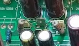
Regarding zobel filter because the used component physical size is so small can it be checked R20/21 is ½w or better and here after amp have had some runtime is value still 20ohm at same check is C14/15 really 47nF.
For a size compare attach copy of member maxwell007 zobel filter.
Regarding zobel filter because the used component physical size is so small can it be checked R20/21 is ½w or better and here after amp have had some runtime is value still 20ohm at same check is C14/15 really 47nF.
For a size compare attach copy of member maxwell007 zobel filter.
Attachments
Last edited:
- Status
- Not open for further replies.
- Home
- Amplifiers
- Solid State
- VSSA Through-Hole Version by Jason