At last I was able to finish the boards. This has been and continue to be a fantastic learning experience for me.
A little cleaning and than testing time..
For testing I bough a 10 Amps 0-140 Volts Powerstat variac.
I also bough the 45 Volts 330RE SMPS.
I need help on the step I should take and any other equipment needed to text the boards.
A few pictures.
Thanks Cesar
Have a look at post #372 linked >HERE< for some presets that should be done before first power up and a recommended set-up sequence. I list there a power cycle using 100Ω resistors, if you choose to do that use 1W resistors since I don't think that 1/4W will stand up reliably to power being applied. The 10Ω also need not be 5W, rather a 1W would be plenty adequate.
You can use your SMPS300RE for testing and set-up but be very certain of your work since you can't control or limit the output from it the way you could with a conventional transformer based supply. If there is an issue with the build it will show up right away. Short across the input connector for the initial testing / set-up. Make sure your amplifiers are properly attached to an adequate heat sink, do not try to do it without.
And BTW, your build is looking very nice so far

Last edited:
Testing VSSA
Hi Jason. I read post #372 several times and it just make my head spin.. I will continued to read it until I do get it.
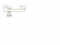
I'm still a little confused on were I should place 100R resistor.
I bough this power supply today Gw Instek GPC-3020 for $80 bucks hoping the I can use it to test the boards..
Thanks
Cesar
Hi Jason. I read post #372 several times and it just make my head spin.. I will continued to read it until I do get it.
I'm still a little confused on were I should place 100R resistor.
I bough this power supply today Gw Instek GPC-3020 for $80 bucks hoping the I can use it to test the boards..
Thanks
Cesar
Attachments
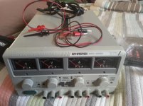

That supply should be fine for initial testing and general bench use. Looks nice for the money spent.
The resistors go 'in-line' with the wires feeding the positive and negative voltages to the amplifier board. They are there for the purpose of limiting current in the event of a fault and you can indirectly measure current by reading the voltage drop across them.
The resistors go 'in-line' with the wires feeding the positive and negative voltages to the amplifier board. They are there for the purpose of limiting current in the event of a fault and you can indirectly measure current by reading the voltage drop across them.
Look at this.Hi Jason. I read post #372 several times and it just make my head spin.. I will continued to read it until I do get it.
I'm still a little confused on were I should place 100R resistor.
I bough this power supply today Gw Instek GPC-3020 for $80 bucks hoping the I can use it to test the boards..
Thanks
Cesar
Attachments
Cesar,
All this said, since you have a nice bench supply you can set the current limit to perhaps 200mA or so and forgo any added resistors that are meant for those without such equipment. You would just turn up the voltage slowly watching for any excessive current draw until you are at full voltage (or 45V, whichever comes first though it looks like the bench supply may have ~30V output).
If you have constructed carefully and followed the first steps on the diagram to get the adjusters pre-set properly then you will likely have an uneventful power-up.
Testing VASS
I will do that as soon as I either buy the amp case or get appropriate heatsink to text the boards..
Man sure takes a lot of different equipment to make this happen.
No regrets though, I'm loving it.. Now I must go shopping again.
Thanks to everyone who has so far help me on this build..
Especially, Jason and Terry
Cesar
Interesting thread/adventiure for the participants.
But having perused 'most' of these Vssa threads. .. I'm still unsure of exactly what the hell this thing actually does? And why people build it.
I'd like to play too..but it seems part of some club adventure.
Just trying to deduce exactly Why it's being built.. Before jumping in.
Basic Due Diligence 🙂
Specs etc. are seemingly 'buried' somewhere else.
The ~$10 pcb (2 rq'd?) is clearly a bargain... What's the Real price though.. by the time the boards are populated.. and a decent PS is conscripted or assembled ?
Also where/how does one get Matched pairs ? barring ownership of Sillyscopes and Hospital power supplies?
Interesting thread/adventiure for the participants.
But having perused 'most' of these Vssa threads. .. I'm still unsure of exactly what the hell this thing actually does? And why people build it.
I'd like to play too..but it seems part of some club adventure.
Just trying to deduce exactly Why it's being built.. Before jumping in.
Basic Due Diligence 🙂
Specs etc. are seemingly 'buried' somewhere else.
The ~$10 pcb (2 rq'd?) is clearly a bargain... What's the Real price though.. by the time the boards are populated.. and a decent PS is conscripted or assembled ?
Also where/how does one get Matched pairs ? barring ownership of Sillyscopes and Hospital power supplies?
Bare,
I'll do my best to answer some of these questions.
What does it do? It is a small to mid sized power amplifier, one board per channel.
I think there are a few reasons why they are being built. They are a fairly simple circuit that is pretty easy to build, even for a relative novice. The sound quality offers a certain something unique to the topology. Very detailed and transparent. You don't need to know any secret handshakes or have a decoder ring to join the fun, just have an open mind.
There are no official specifications, I don't think anyone has measured one with total objectivity using laboratory equipment. All anyone can say is it is fast and good for about 100W into 4Ω.
No matching is actually required, it just helps us get the best from a simple circuit. The transistors can be had for about $12 total, I get the MOSFETs for 4.99 each and the rest are about $0.20 each. You don't have to break the bank on the rest either, but setting aside a few dollars for quality caps seems popular. Nothing exotic, just good Nichicon, Panasonic, Elna or similar.
A simple unregulated linear supply will work just fine, or a ready made SMPS is also attractive. No need for over the top with excess capacity.
I spent about $230ish to build a stereo pair in a small all aluminum chassis with a nice SMPS and all the little goodies like binding posts and input jacks. Building with some recycled items like heat sinks and transformers can reduce costs quite a bit.
Hope you won't mind me helping , JK ...
Very simple amp with actually better specs than many OEM's.
-Worst case .005% THD across the audio spectrum.
-Noise is typically -100db + .
-very wide bandwidth limited by input filter/cap (5hz - 200K+)
Results can be much better ... but only slightly worse. This all
depends on build quality and component choices.
OS
OS
Also can go here our siliconray store Search results for: 'enclosure' - Boards | Kits | Components | Modules | Tools
Our store also have Variety of chassis.
Our store also have Variety of chassis.
Hi BareI'd like to play too..but it seems part of some club adventure.
As a thread starter few words from me. VSSA acronym stands for Very Simple Symmetrical Amplifier and that exactly explains its nature. It was a big DIY "club" last year, meaning group buy of several hundreds kits in which very special output transistor was used: ALF08NP16V5 from Semelab. PCB size was only 50 x 60 mm and that includes double output transistor.
VSSA mania started from there on and it seems people still have fun with it.
Regards, L.C.

Thank you All gents.. apologies if reading as unpleasant.. wasn't any such intention.
Merely having trouble getting info for deciding whether to try one of these rascals for myself.. Yess 😱
Merely having trouble getting info for deciding whether to try one of these rascals for myself.. Yess 😱
Build it. You won't be sorry. Jason has designed a nice PCB here. It goes together very well and he is always around with kind help. All easy to get parts. Doesn't need a large heatsink and will run on a wide voltage range. Oh, did I mention it sounds lovely?
Blessings, Terry
Blessings, Terry
I'm in.. Newbie though 😱
Reading from the supplied Mouser bom ..I'm needing to add resistors and the red Leds for css ?? Can ANY leds be used?
Previous work with a Css clearly required a specific (and hard to track down) red LED.
Anything else not on that list that I should know about ?
Don't know, just asking.
Or do I buy leds and required resistors at the local Cheap Chinese Parts 'hole in the wall' shop ? They have a fairly good stock of, albeit (usually) Fake parts 😉
Erm...how does one actually order from Mouser ?
Whom I presume does ship to Canada, sans usurious border fees?
Thank you
Check this post for a good LED to use: http://www.diyaudio.com/forums/soli...hrough-hole-version-jason-18.html#post3820856
What you want is a basic red LED (not high efficiency or high output type). They have the lowest dynamic impedance of the LED's. Your local source may be fine.
Sheldon
What you want is a basic red LED (not high efficiency or high output type). They have the lowest dynamic impedance of the LED's. Your local source may be fine.
Sheldon
Your link is not working. What Post # were you referring to?Check this post for a good LED to use: http://www.diyaudio.com/forums/soli...hrough-hole-version-jason-18.html#post3820856
What you want is a basic red LED (not high efficiency or high output type). They have the lowest dynamic impedance of the LED's. Your local source may be fine.
Sheldon
EDIT: found it. http://www.diyaudio.com/forums/solid-state/250097-vssa-through-hole-version-jason-5.html#post3830180
Last edited:
The CCS is either two transistors or one and an LED, not both. The two transistor type is my default choice, other options I leave to those who know what they want.
Great thanks..
Not wanting to add any complexity and clearly have No experiences on what I want Or works 'better'.
Only that leds were used in my past, wasn't aware that they weren't the only path.
More 'Trust' is implied then ? 🙂
Not wanting to add any complexity and clearly have No experiences on what I want Or works 'better'.
Only that leds were used in my past, wasn't aware that they weren't the only path.
More 'Trust' is implied then ? 🙂
- Status
- Not open for further replies.
- Home
- Amplifiers
- Solid State
- VSSA Through-Hole Version by Jason