How is this solvent on solder mask. I have been using methanol but it seems to smear the solder mask.
Thanks, Terry
Thanks, Terry
I like to clean up with isopropyl alcohol. Doesn't damage silk or mask. After that, you can make them really clean with an aerosol brake cleaner and compressed air.
Build update.
The passed few days I study all the photos and I reread the entire forum again.
Watch some videos on how to solder.
The results are better than my first try.
Check post 323 and compare.
All feedback are welcome.
Jason thanks for the encouraging words.
That soldering is looking much better Cesar. With a little more practice you will have the perfect amount of solder so that the pads on the top and bottom are just right, every time. If the solder doesn't wick through to hole right away you can reposition the soldering iron tip just a little and leave the heat on for just a couple seconds more.
I'm happy to see you taking this slow and easy, not rushing into the build. When you are ready we will go through 'pre-setting' the adjusters and how to properly set these up. It isn't hard to do but will need you to take your time and work with care.
How is this solvent on solder mask. I have been using methanol but it seems to smear the solder mask.
Thanks, Terry
Terry,
It Works like a charm. Does not bother the mask at all. It WILL Dry out your hands if you get it on them. Use with care & good Ventilation.
Agreed, it may not sound as wonderful as the exotic solvents but it's safe enough and there may be enough in the home without making a trip or trying to get flammable liquids shipped to you......Or you can try Alcohol, the 99% pure type.
Standard industrial alcohol or methylated spirit is denatured with methanol and often benzene and pyridine which will attack ink/paint etc. The trick I have used for many years is to add enough water to this cheap alternative (about 10% but depending on your local product content) to prevent the attack on the paint but still work acceptably on the flux rosin. This stuff is as little as 10% of IPA or pure alcohol cost, is everywhere and so it's worth consideration.
If anything in a bottle scares you, good old piping hot water from the household supply works just fine with the encouragement of an old toothbrush too.
Power supply help
Hi Jason. Did you decided which SMPS to use with the VASS.
Almost finish the boards, so I believe I will need some type of power to set up and test the boards.
Can you recommend a inexpensive table top power supply for testing.
Will post some pictures later..
Hi Jason. Did you decided which SMPS to use with the VASS.
Almost finish the boards, so I believe I will need some type of power to set up and test the boards.
Can you recommend a inexpensive table top power supply for testing.
Will post some pictures later..
If you are looking for an inexpensive SMPS that can be used for testing, I bought one of these. One nice thing about it is that if it gets over amped it will cycle on and off. Down side is it won't work with the light bulb tester. Best thing to do is use 100R 1/4w resistors inline to limit current and act as fuses if there is a problem. +-25V is enough to power the amp.
Last edited:
Hi Jason. Did you decided which SMPS to use with the VASS.
Almost finish the boards, so I believe I will need some type of power to set up and test the boards.
Can you recommend a inexpensive table top power supply for testing.
Will post some pictures later..
Hi Cesar,
I have actually not yet settled on a firm recommendation. I'm actually biting the bullet and getting a few different ones and can give better impressions when I have units on hand. Despite my current issue with a Connexelectronic SMPS500R that is being sent back, for the price get one of their SMPS300RE units in the +/-36V output. I suggest using the vendor HiFimeDIY out of the US warehouse. Links:
HiFimeDIY US Store
SMPS300RE +-36V (dual voltage) 110V Power Supply
For testing and initial set-up I actually recommend using a plain vanilla linear supply if you can, at about the final output voltage you are planning on using. That way you can use a 'bulb limiter' (a must for any DIY'er) and a variac (nice to have but not essential) to help with fault finding and reduce the chance that an error will result in damaged parts.
For that a smallish ~100VA 26-0-26 (centre tapped or dual secondary, from 24V to 26V per tap or winding) transformer, mains fuse, switch, bridge rectifier, filter capacitors (smallish, maybe ~4700µF @50V), bleeder resistors and output fuses would make for a nice little 'bench supply' that can be used for testing other things later on. Put all that in a cheap project box with binding posts to connect to the projects needing power. The bulb limiter is an add-on the feed the small linear supply.
If you just want to get one supply and do the testing off the final supply then I suggest initial power-up be with a pair of 1/4W 100Ω resistors in the supply lines. If all is good then initial set-up can be done with a couple of 5W 10Ω resistors be put in-line with the +/- supply lines at. Final verification is done on an unlimited supply. Let me know when you are fully ready and we will walk through some initial set-up.
I know you have been studying the photos but the very first thing is a careful check of your work. Look for missed solder joints, joints that are shorted together (solder bridges), incorrect components / values, etc. one satisfied all looks good we will pre-set the adjusters before we power up for the first time.
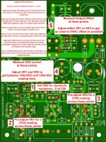
Suggested Set-Up Sequence
Hopefully this will assist with setting up the boards for those who aren't familiar with the VSSA already.
This is easiest with more than one multimeter and test leads with small alligator clips if you have them. It can be done 'fully manual' with one meter and regular leads if need be. Just make sure you are slow and careful with set-up to avoid shorting something out with a slipped test lead tip.
Please Note: If properly pre-set VR1 and VR3 won't need large adjustments. If you feel like you are turning them too much, you probably are. Stop! Power off and start over. An anecdote; I had one test lead on a test module that wasn't in good contact when measuring the VAS current resulting in a false reading. It resulted in me turning the adjusters too low and popping the VBE and a 100Ω gate stopper. No major damage, but still a repair all the same.
Attachments
Very helpfull Jason but one question does the input need to be shorted for the offset measurement?
Very helpfull Jason but one question does the input need to be shorted for the offset measurement?
It certainly can't hurt to short the input, but it doesn't float either with the 100kΩ across the input. I haven't seen any significant difference either way, just don't attach any cables to the input before they are tuned.
Very helpfull Jason but one question does the input need to be shorted for the offset measurement?
Yes, whether the input is DC or AC coupled, shorted input simulates source's (preamp) low output Z and zero output DC. Also prevents unwanted EMI signals to enter sensitive input among measuring phase, while holding the amp in very steady condition.
DC coupled input transfers source's (preamp) output DC offset with gain 1 (AC coupled GNFB) or full gain (DC coupled GNFB) to the output. In this sort of connection any other than zero input DC calibration condition (shorted input) would cause certain output DC offset when zero DC source would be connected.
AC coupled input cuts source's (preamp) output DC offset influence completely. Now the source of output DC offset is the amp's input stage unsymmetry, driven by thermal changes practically in all stages.
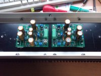
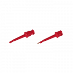
Boards are soldered now adjusting have ordered some special clips for that
Attachments
Last edited:
- Status
- Not open for further replies.
- Home
- Amplifiers
- Solid State
- VSSA Through-Hole Version by Jason