No, no, standard parts on 50 x 80 mm PCB, only that I will use these output mosfets, ordered four. 😀
Why 4? did plan to use more than one per chanel???
Will be 8A devices to drive 4 to 5ohms min speakers at +/-35VDC rails?
Marc
Last edited:
Why 4? did plan to use more than one per chanel???
Will be 8A devices to drive 4 to 5ohms min speakers at +/-35VDC rails?
Marc
One ALF08NP16V5 per channel. Look it is simple, for Id=8A you need Vgs=6V, so at +/-38V PSU you get +/-32Vp on the output and that is 8Ap current. This device can do 8A continuos current within SOAR. So perfectly OK for one ALF08NP16V5 to drive 4 ohm at +/38V rails potential and you get out 128Wmax/4 ohm. 😉
One ALF08NP16V5 per channel. Look it is simple, for Id=8A you need Vgs=6V, so at +/-38V PSU you get +/-32Vp on the output and that is 8Ap current. This device can do 8A continuos current within SOAR. So perfectly OK for one ALF08NP16V5 to drive 4 ohm at +/38V rails potential and you get out 128Wmax/4 ohm. 😉
Who very interesting....i think i have little home work on eagle this evening...
Marc
Look Marc here's VSSA PCB preliminary. All three transistors to main heatsink, TO-126 will have 2 mm ceramic insulators, so very little capacitance to main heatsink (GND) and still enough heat dissipation. PCB fixed with these three screws only, each 2,2 mF/40V replaced with two 1mF/50V, etc. So you can get an idea ... 😎
Attachments
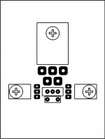
Look Marc here's VSSA PCB preliminary. All three transistors to main heatsink, TO-126 will have 2 mm ceramic insulators, so very little capacitance to main heatsink (GND) and still enough heat dissipation. PCB fixed with these three screws only, each 2,2 mF/40V replaced with two 1mF/50V, etc. So you can get an idea ... 😎
Rhaaa lovely....will play with that if allow.
Marc
cool looking little amp
maybe time to go build that active speaker 🙄
Yes, VSSA PCB will be perfectly suitable for that purpose, just wait a little. 😉

Sonny.. Regarding the tendency for the VAS to run thermally away, I have seen that a thermistor across the 470 Ohm rail resister can balance that out. I have currently two amplifiers playing, one bare stripped to simplest basic (like this) and one with everything. CCS's mirror's hawksford-casodes (input and VAS/Driver). Have not yet heard them in the same setup, but sometime during January I will... But first I need to cut some diamond for the CES.🙂
ALF08NP16V5 board try : 75x66mm
Very good.

It will take me some more time but will do it anyway. 😀
But first I need to cut some diamond for the CES.🙂
This time you won't get away without showing us some pics.

Very good.
It will take me some more time but will do it anyway. 😀
Thanks LC, i think i will order a ALF08NP16V5 couple next day.
Marc
hi Lazy Cat
Can you do symmetric 50V version ?
Symmetric it is already.

I promised Bigun not to mess with more complexity, because what you want would transform VSSA into cascodes for input pair, two output pairs with extra drivers, etc. That is what you can probably do by yourself in no time.

Member
Joined 2009
Paid Member
Yes, good to stick to the plan here - 'very simple' means few parts. It means we are accepting some compromises. We can add complexity to deal with all sorts of things and improve the on-paper performance. In fact, you did that already with SSA.
What can be achieved with simple approach, where debugging is easy, pcb layout can be more optimal. Heck, can you make it simple enough for point to point so anybody can build it ?
What can be achieved with simple approach, where debugging is easy, pcb layout can be more optimal. Heck, can you make it simple enough for point to point so anybody can build it ?
Heck, can you make it simple enough for point to point......
I thought it already is that 🙄
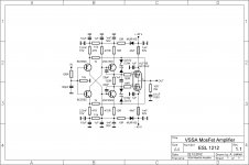
VSSA MosFet Amplifier V1.1
Hi
VSSA schematic update. ALF08NP16V5 new double complementary output mosfet successfully tested, some design improvements and gate zener protection included. This is very good simple amplifier, highly recommended.
Hi
VSSA schematic update. ALF08NP16V5 new double complementary output mosfet successfully tested, some design improvements and gate zener protection included. This is very good simple amplifier, highly recommended.
Attachments
Very nice circuit!
Congrats
With the help of wahab my darlington also was converted to Hitachi lat mosfet amp..
Greetings Gabor
Congrats
With the help of wahab my darlington also was converted to Hitachi lat mosfet amp..
Greetings Gabor
Last edited:
Khewwwwlll..... It's very easy for you, huh? Looking forward to see the highest (optimum) power possible with this topology (no less than 100W) without sacrificing the overall performance.
I would love to see a sim test on both amplifier..
I know sim does not gave 100% justice about sound performance but still give you some hint.
I do not post the circuit here (to avoid confusion, and by respecting your nice work) only some ref so you can find it easily.
post #237 here
http://www.diyaudio.com/forums/solid-state/133189-my-firs-diy-amplifier-20-years-go-24.html
Greetings Gabor
Hi
VSSA schematic update. ALF08NP16V5 new double complementary output mosfet successfully tested, some design improvements and gate zener protection included. This is very good simple amplifier, highly recommended.
Hi LC,
need i some value tweakking to keep rail voltage to +/-35vdc as in first version (nice 625Va or 2x300va 2x25vac i have)
Marc
- Home
- Vendor's Bazaar
- VSSA Lateral MosFet Amplifier