Dear Lazy Cat,
About CCS, wouldn't it be better to instal a JFET cascode?
BF245 are inexpensive and I have a lot... 🙂
Thank you.
M.
Speaking about the input pair transistors there's a lot of things which can be implemented to "enhance" the performance, so I thought. Tried BJT cascode, j-fet cascode, tracking cascode, all measured good but listening tests rejected one after another. The best solution soundwise for an input pair transistors is very high Vce, close to its max, so Cbc is minimal and almost constant regardless the level of modulation signal. The only thing an input transistor likes in its collector current loop is pure resistance, without any leakage current paths caused by cascodes.

I don't recommend this for several reasons.
This will make the DC offset less stable. This will encourage-you to use higher impedance source, witch is not optimal for sound quality: More sensible to ground loop noises, little more distortion, more change of quality depending the position if the source is a potentiometer etc...
Thank you Christophe, explained in very exact manner. 10 k input impedance is a sweet spot for a power amplifier. Any high impedance sources should be connected via apropriate input buffer or a preamp gain stage, with no DC offset. By using 10 k input impedance also no DC servo is required for VSSA. 😉
.....I add here some pictures with details, to spare a lot more Words..........
Very fine pictures, sorry those details so good and makes quistion: 50V AC then 71V DC smoothers, is that safe or is ESP (Rod Elliott) tips curing the danger and hidden behind caps.
Expect no answer preliminary, imagine no one can get you from speakers sweet spot listening all your material through......😀.....

Speaking about the input pair transistors there's a lot of things which can be implemented to "enhance" the performance, so I thought. Tried BJT cascode, j-fet cascode, tracking cascode, all measured good but listening tests rejected one after another. The best solution soundwise for an input pair transistors is very high Vce, close to its max, so Cbc is minimal and almost constant regardless the level of modulation signal. The only thing an input transistor likes in its collector current loop is pure resistance, without any leakage current paths caused by cascodes.
OK. Thank you very much, LC.
I will study you comments and probably will do comparisons as time allows.
M
It is incredible how VSSA is an egg. Perfectly optimized. Every little change you can try breaks the magic.10 k input impedance is a sweet spot for a power amplifier. Any high impedance sources should be connected via apropriate input buffer or a preamp gain stage, with no DC offset. By using 10 k input impedance also no DC servo is required for VSSA. 😉
This said, i would realy like you try my suggestion to remove caps in the feedback patch, when you'll have one free hour. It don't add a pole in the feedback path, will reduce distortion a digit and even more at low frequencies. It don't change your structure as well and i hope, will not have the Diamond buffer's negative effects you noticed (me too ;-). The only thing i don't know is if the added DC gain don't add too much offset rock'n roll (one for the money, two for the show).
Talking about feedback caps, I have troubles finding suitable film caps of reasonable size and price but I found some little 10uF/16V SMD caps (X5R) that I would probably try. Never used them but tempted due to small size and cost.
50x Samsung Series CL 10uF 16V SMD 1210 Ceramic Capacitors X5R 10 | eBay
What do you think?
Cheers,
M.
50x Samsung Series CL 10uF 16V SMD 1210 Ceramic Capacitors X5R 10 | eBay
What do you think?
Cheers,
M.
Very fine pictures, sorry those details so good and makes quistion: 50V AC then 71V DC smoothers, is that safe or is ESP (Rod Elliott) tips curing the danger and hidden behind caps.
Expect no answer preliminary, imagine no one can get you from speakers sweet spot listening all your material through......😀.....
Not really listening now. I built the balanced converter using 4580 JRC IC's and while they are almost OK for listening, you cannot do much for measurements. The square wave starts to be skewed from about 10kHz, and they start to clip at a voltage that translates to 79,2V p-p at the output of the amplifier. After I noticed that the amplifer clips so early, I checked the output of the adapter and the clip was there as well 🙁
Probably the best would be to use JC-80 itself as the balancer, but I wanted to test only the power itself.
At almost 80V between peaks delivered to 8 OHMS resistive load, the amp was already hot after 15 minutes, but the 80C sensor did not trip off the power supply; probably best would have been a 4U box instead of the 3U used in current project.
Still have some DRV134 at hand, probably those would work better. Will see if I'll have the power to build another box in the weekend.
About the caps voltage, they are fine. In my place there are no huge voltage variations, always 231V at the outlet; tested the smoothers with the Variac supply, and at 75V they still did not show a noticeable DC current, and that looks OK for me; the only reason of concern was the 85C spec, that is why I have mounted them as far away from the heatsinks as possible.
Cheers!
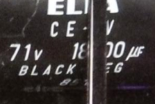
Confused when i see on cap 71v.....at 75V they still did not show a noticeable DC current, and that looks OK for me; the only reason of concern was the 85C spec, that is why I have mounted them as far away from the heatsinks as possible....
 (see picture just before 18.000uF), at same i am sure it is under control 😎 just curious.
Attachments
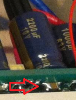
See beneath maybe usefull...........What do you think?.....
..........I very much like your findings that parallel film cap across elco is an improvement, for the same reason I provided both 10 uF in VSSA. I also found out that this cap should have non resonant high-Q dielectric material, like film caps are. 😉..........
Last edited:
It is incredible how VSSA is an egg. Perfectly optimized. Every little change you can try breaks the magic.
This said, i would realy like you try my suggestion to remove caps in the feedback patch, when you'll have one free hour. It don't add a pole in the feedback path, will reduce distortion a digit and even more at low frequencies. It don't change your structure as well and i hope, will not have the Diamond buffer's negative effects you noticed (me too ;-). The only thing i don't know is if the added DC gain don't add too much offset rock'n roll (one for the money, two for the show).
I will try it out with the First One channel which will be assembled over the weekend. Now we have 12-15 mA VAS bias current temperature fluctuation, after FB caps removal there will be more, hopefully still acceptable. Anyhow this will not influence output bias at all. Will be tested.

... three to get ready, now go, cat, go. 😀
Speaking about the input pair transistors there's a lot of things which can be implemented to "enhance" the performance, so I thought. Tried BJT cascode, j-fet cascode, tracking cascode, all measured good but listening tests rejected one after another. The best solution soundwise for an input pair transistors is very high Vce, close to its max, so Cbc is minimal and almost constant regardless the level of modulation signal. The only thing an input transistor likes in its collector current loop is pure resistance, without any leakage current paths caused by cascodes.
LC, how about VAS cascode or VAS beta enhance? I have no time right now to try, but I found 20mA VAS using BD trainies is better in treble (subjectively).
Thanks to your clever shunt voltage regulator, very well compensated in temperature.Anyhow this will not influence output bias at all.
Confused when i see on cap 71v
Yes, that is the maximum voltage recommended by the producer, usual caps can tolerate a bit more. In my setup, with 360mA static bias of one channel it stays around 70V. Nothing to be worried about.
I will try it out with the First One channel which will be assembled over the weekend. Now we have 12-15 mA VAS bias current temperature fluctuation, after FB caps removal there will be more, hopefully still acceptable. Anyhow this will not influence output bias at all. Will be tested.
... three to get ready, now go, cat, go. 😀
Hi LC, have an idea when you will release First One?
Some guy here in france will be interest....me the first..
Marc
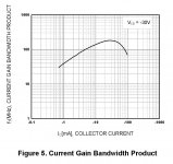
LC, how about VAS cascode or VAS beta enhance? I have no time right now to try, but I found 20mA VAS using BD trainies is better in treble (subjectively).
Higher current makes it have higher current gain bandwidth product. 😉
Why don't you try both, beta enhancer plus tracking cascode.

Regards Lazy Cat

Attachments
Hi Marc 
Today I'll get few samples of completely new and redesigned First One's PCB.
Over the weekend two will be assembled, tested next week, all new data collected and stored.
In december one thousand PCB-s will go into SMD assembly. Than all TH parts will be soldered gradually according to orders intensity.
Well at least that's the plan.
Maybe this guy will have some more work to do hehe 😀
Today I'll get few samples of completely new and redesigned First One's PCB.
Over the weekend two will be assembled, tested next week, all new data collected and stored.
In december one thousand PCB-s will go into SMD assembly. Than all TH parts will be soldered gradually according to orders intensity.
Well at least that's the plan.
Maybe this guy
will have some more work to do hehe 😀Hi Marc
Today I'll get few samples of completely new and redesigned First One's PCB.
Over the weekend two will be assembled, tested next week, all new data collected and stored.
In december one thousand PCB-s will go into SMD assembly. Than all TH parts will be soldered gradually according to orders intensity.
Well at least that's the plan.
Maybe this guy
Ok Thanks LC, I will relay info on french forum...
Marc
OK. I got it.Thank you. 🙂
More spy info see picture from "First One" prestage. If it's SMD-film, SMD-ceramic or changed since don't now (Link: http://www.diyaudio.com/forums/solid-state/239708-vssa-50-a-5.html#post3598917).
Attachments
..........(one for the money, two for the show).
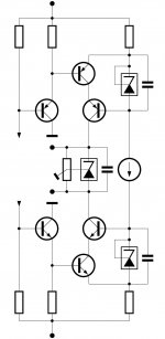
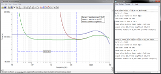
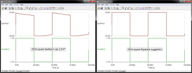
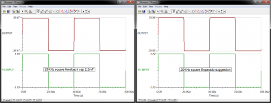
Played with simulation of GB circuit (copyrighted so please don't ask schematic other than Andrej). Implemented Esperado schematic from post #2629 the best my hobbist skills allow, remember it's simulation only. The audio band group delay gets perfect linear when zoomed into nano seconds. Christope i am in doubt about truth for 20Hz square, could result be right ?..........three to get ready, now go, cat, go. 😀
Attachments
Last edited:
- Home
- Vendor's Bazaar
- VSSA Lateral MosFet Amplifier