To bimo and analog_sa, the only way to get an answer to your question is to... try by yourself. 🙂
Maximum ULGF is only the one you can get stable with your real build, ...experimenting.
Today, I have experimented another type of compensation. It is stable with 100nF capacitor parallel with speaker. With VAS using BD139 and BD140, it is stable without compensation (maybe depend on PCB layout and my PCB layout is good enough 😎). And I try another tranies for VAS.
I am learning to simulating SSA front end with cascade VAS. It give less distortion by > 10x than VSSA, but difficult to compensated. Maybe SSA is my next project.
LC, you are my hero....
Last edited:
It's with joy to read that all your care/knowledge combined with Andrej's care/knowledge for the VSSA module when united has payed back. Again as in other thread, thanks for equip us members with your technical tricks with description.......Another VSSA is finished...really impressed by the sound.....


Last edited:
Because i was curious (and nice ;-), i tried a quick'n dirty simulation with Jfets in input stage.
(Remember it is just a simulation, but comparing makes sens).
Current sources for Jfets set to 600µA to get 10ma in VAS (as in VSSA)
Models for the Jfets from the Orcad library.
Current in drain of the Jfets: 1.7mA. Gates with 100K.
Everything else unchanged (it can be improved, but no more the same amp at all ;-)
Results as expected:
BC 560+ BC550 1KHz : HD = 0.000765
J2sk246+J2sj103 1KHz : HD = 0.005427
BC 560+ BC550 20Khz: HD = 0.011288
J2sk246+J2sj103 20KHz: HD = 0.086734
Make your mind.
It can decrease distortion, reducing slew rate and ULGF, with some problems with square waves ?...
The question about the actual distortion is: Can-we ear-it ?
Is more complex signal path don't bring evil effects in listening experience, despite those better numbers ?
(Remember it is just a simulation, but comparing makes sens).
Current sources for Jfets set to 600µA to get 10ma in VAS (as in VSSA)
Models for the Jfets from the Orcad library.
Current in drain of the Jfets: 1.7mA. Gates with 100K.
Everything else unchanged (it can be improved, but no more the same amp at all ;-)
Results as expected:
BC 560+ BC550 1KHz : HD = 0.000765
J2sk246+J2sj103 1KHz : HD = 0.005427
BC 560+ BC550 20Khz: HD = 0.011288
J2sk246+J2sj103 20KHz: HD = 0.086734
Make your mind.
Yes, that's all the problem with added poles.It give less distortion by > 10x than VSSA, but difficult to compensated.
It can decrease distortion, reducing slew rate and ULGF, with some problems with square waves ?...
The question about the actual distortion is: Can-we ear-it ?
Is more complex signal path don't bring evil effects in listening experience, despite those better numbers ?
Last edited:
metallicus69
It is great encouragement to see such meticulous standards of workmanship.
You clearly have experience of other high end cartridge amps. When your Paradise has settled down please do tell us how it compares with others.
It is great encouragement to see such meticulous standards of workmanship.
You clearly have experience of other high end cartridge amps. When your Paradise has settled down please do tell us how it compares with others.
Thanks for the kind words!
The finishing of my builds is not top looking, but exactly this aim kept me down for finishing anything until this year.
I changed this, and I prefer to have components just decent enough to be part of the living room setup, but as good as possible in performance.
Regarding Paradise, it's quite off topic here. I can only say it's still the best phono preamplifier I've ever heard, no matter what music style touches the stylus of the cartridge. I am not good in describing the sound character so I will just stop to this statement.
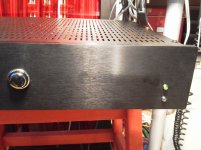
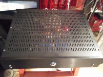
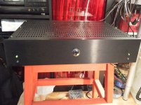
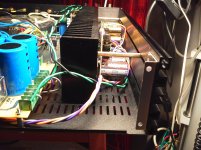
Back on topic, I add a few pictures related to show how I finished this VSSA, which is a great companion to Paradise and JC-80 analog chain. Please excuse the quality of the photos and don't laugh too much about my choice of a game console switch for start-stop (the only acceptable one i had around). 😀
Each channel has a pair of LEDs for on/protect indicators of the speakers output. The position was picked up for practical reasons, as the modushop front panel has some grooves there and it's thick enough to allow me to mount them.
Cheers!
The finishing of my builds is not top looking, but exactly this aim kept me down for finishing anything until this year.
I changed this, and I prefer to have components just decent enough to be part of the living room setup, but as good as possible in performance.
Regarding Paradise, it's quite off topic here. I can only say it's still the best phono preamplifier I've ever heard, no matter what music style touches the stylus of the cartridge. I am not good in describing the sound character so I will just stop to this statement.
Back on topic, I add a few pictures related to show how I finished this VSSA, which is a great companion to Paradise and JC-80 analog chain. Please excuse the quality of the photos and don't laugh too much about my choice of a game console switch for start-stop (the only acceptable one i had around). 😀
Each channel has a pair of LEDs for on/protect indicators of the speakers output. The position was picked up for practical reasons, as the modushop front panel has some grooves there and it's thick enough to allow me to mount them.
Cheers!
Attachments
Hi L.C.,
Another VSSA is finished.
I am really impressed by the sound, and in the same time by the silence when it should be 🙂 The first moment I connected the speakers I thought I have a broken cable, a destroyed connector, or something missing in the chain. I could hear nothing with my ear "glued" to the speaker. it's really the first time for me to experience this.
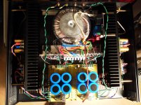
As posted in other sister threads, I use a toroidal transformer custom built for audio, 500VA with separate outputs for each rail, each channel. Each output goes to a dedicated discrete rectifier bridge (4x IXYZ soft recovery) that feeds a capacitor multiplier (Mr.Evil/PMI) via 2x15.000 uF on each rail. It might be an overkill, but I prefer to have more than too little.
With complete separate ground lines, I kept the GND - separating resistors on board, and i replaced by a wire each D-R group that feeds the VAS. The case is connected to each GND by a lifting DDRC group for each channel, coupled in the same point where the transformer's screen meets the chassis.
I would like to thank everyone that constructively contributes to DIYaudio discussions, and especially to Andrej for providing such a masterpiece to this nice community.
Cheers!
What is your rail voltage? Have you measured maximum p-p voltage output?
Your build is quite good looking and well laid out. Congrats.
Just curious.
Wow this is a mighty long thread.
Can someone point me to the final version of the amp?
Also is there a version with two pairs (or more) of output transistors?
Thanks
Can someone point me to the final version of the amp?
Also is there a version with two pairs (or more) of output transistors?
Thanks
Can someone point me to the final version of the amp?
It's unpublished but very close to 1.4
Thanks!What is your rail voltage? Have you measured maximum p-p voltage output?
Your build is quite good looking and well laid out. Congrats.
Just curious.
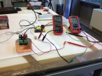
My supply voltage is +/- 36.5V right after the voltage multiplier. A bit more than +/-37V on the main reservoir caps. Although fed by different transformer outputs, they are identical in the mV range between the channels and polarities.
I did not measure the p-p output voltage, I just expect it to be close to 60V as the supply voltage does not collapse significantly under heavy drive. Will probably make some tests in the near future and report.
Cheers!
Folks / Lazy Cat,
Anyone know if there are any boards left or all they all gone? Any discussion of the next GB if they are all gone?
Anyone know if there are any boards left or all they all gone? Any discussion of the next GB if they are all gone?
Hi ,
Im my case i got 4,0v output bias, 120mv input bias, but my offset is 372 mv in one channel and 350mv in other channel. I get lower offets only if input bias is 70-80mV.
The sound is very good but i can't get lower bias.
Any inputs ?
cheers
Im my case i got 4,0v output bias, 120mv input bias, but my offset is 372 mv in one channel and 350mv in other channel. I get lower offets only if input bias is 70-80mV.
The sound is very good but i can't get lower bias.
Any inputs ?
cheers
Hi ,
Im my case i got 4,0v output bias, 120mv input bias, but my offset is 372 mv in one channel and 350mv in other channel. I get lower offets only if input bias is 70-80mV.
The sound is very good but i can't get lower bias.
Any inputs ?
cheers
Hello hcbonfim,
your offset is definitely too high. Try this, turn TR1 fully counterclockwise, with TR2 set 0 mv offset and then raise input bias with TR1 to 120mV.
Regards
Marko
Nice tip mkusan , did you have the similar issue ?
thanks a lot , i will try
cheers
Not really, it took me five minutes from first power-up. I settled for 122mV input bias and 1mV offset.
I should have been more precise, after you set 0mV with TR2, set slightly lower bias 100-110mV with TR1, hopefully turning again TR2 would reduce offset to zero and increasing the bias to 120mV at the same time.
Hopeit helps
Marko
Take my speech, solely as a help or info. no other reasons please.
As I said earlier in this thread, this amplifier is EXTREMELY simple and ingenious, certainly fast with nice sound, but this simplicity comes at a price to be paid. Requires a well-regulated power supply. not only for the problems as thermal drift, but for the huge imbalance provided by an SMPS unregulated during transients. the amplifier is "discovered" from this point of view. so it takes a well-regulated psu, better with quick response.
regards
Take my speech, solely as a help or info. no other reasons please.
As I said earlier in this thread, this amplifier is EXTREMELY simple and ingenious, certainly fast with nice sound, but this simplicity comes at a price to be paid. Requires a well-regulated power supply. not only for the problems as thermal drift, but for the huge imbalance provided by an SMPS unregulated during transients. the amplifier is "discovered" from this point of view. so it takes a well-regulated psu, better with quick response.
regards
AP2,
Which of your SMPS would be ideally suited for this amplifier?
Thanks
Do
Sure, Roberto ? Not the slighest commercial attempt ?Take my speech, solely as a help or info. no other reasons please.
As I previously reported, the best solution will be to provide a separated low noise regulated supply for the Input + VAS only. Only +-20mA needed. Preferably linear. No need for Regulated high Amp psu to feed the OPS. As they are not fast enough, compared to the OPS speed, they usually are not so good, sonic side, bringing some recovery artifacts after transients. Caps multipliers are better, here.Requires a well-regulated power supply. not only for the problems as thermal drift, but for the huge imbalance provided by an SMPS unregulated during transients. the amplifier is "discovered" from this point of view. so it takes a well-regulated psu, better with quick response.
All CFA suffer from limited PSSR, specially in common mode. Not far from any VFA, in differential mode.
I believe this amp had been tested and recommended by L.C. with a well known unregulated SMPS (from Hypex) witch is known to be highly symmetrical.
Any offset will not come from this side, apart some failure.
This said, why did-you not proposed to L.C. to try one of your SMPS with this amp ? May-be some good surprise .
Last edited:
- Home
- Vendor's Bazaar
- VSSA Lateral MosFet Amplifier