Sure, Roberto ? Not the slighest commercial attempt ?
As I previously reported, the best solution will be to provide a separated low noise regulated supply for the Input + VAS only. Only +-20mA needed. Preferably linear. No need for Regulated high Amp psu to feed the OPS. As they are not fast enough, compared to the OPS speed, they usually are not so good, sonic side, bringing some recovery artifacts after transients. Caps multipliers are better, here.
All CFA suffer from limited PSSR, specially in common mode. Not far from any VFA, in differential mode.
I believe this amp had been tested and recommended by L.C. with a well known unregulated SMPS (from Hypex) witch is known to be highly symmetrical.
Any offset will not come from this side, apart some failure.
This said, why did-you not proposed to L.C. to try one of your SMPS with this amp ? May-be some good surprise .
Hi,
I proposed to L.C.s to try a particular model, which I think is perfect for this amp, and maybe even a very affordable price in case of GB.
I have not seen interest, and I'm not the type of person who pushes a product, or as others who are able to say "it's perfect" just to sell. having said that, just to clarify, my speech is not tied to any desire to sell a smps.
Technically, you already know how I feel on the voltage that needs to be firmly under the transients. this can not be an "opinion" but a demonstrable fact.
The problem is that the "others" want to feel free to bla .. bla .. and my comments are unwelcome.
My intervention is absolutely no commercial interest.
Good weekend at all.
I was just teasing-you, Roberto. I know you are a nice guy.and my comments are unwelcome.
If you had proposed a SMPS in test to L.C., i believe he did not saw your post or email.
Lot of problems of communication with him, those last time.
From what I have tried so far, there is definitely a benefit from using a better/cleaner power supply, but I think anyone will be rewarded with great sound with some care and normal precautions. My overall experience with VSSA has been excellent.
I have built three versions so far, including the simplest circuit proposed by Shaan in the PeeCeeBee thread, another version close to the 1.4 rev schematic, the third one being the modules from this thread.
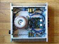
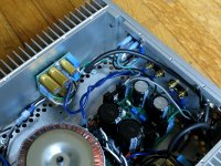
The pics below are the VSSA modules from the first GB, with my version of Mr. Evil's Capacitance Multiplier power supply.
Same circuit Metallicus mentioned in Post 2580.
Heatsinks are from HeatsinkUSA.com, one of the advertisers on diyaudio.
Transformer is plain vanilla AvelLindberg 330VA/25V.
Power supply voltage is adjusted to +/-36V at idle.
One of these days I hope to try a version with a separate supply for the front end as Esperado suggested above.
I have built three versions so far, including the simplest circuit proposed by Shaan in the PeeCeeBee thread, another version close to the 1.4 rev schematic, the third one being the modules from this thread.
The pics below are the VSSA modules from the first GB, with my version of Mr. Evil's Capacitance Multiplier power supply.
Same circuit Metallicus mentioned in Post 2580.
Heatsinks are from HeatsinkUSA.com, one of the advertisers on diyaudio.
Transformer is plain vanilla AvelLindberg 330VA/25V.
Power supply voltage is adjusted to +/-36V at idle.
One of these days I hope to try a version with a separate supply for the front end as Esperado suggested above.
Attachments
I have built three versions so far, including the simplest circuit proposed by Shaan in the PeeCeeBee thread, another version close to the 1.4 rev schematic, the third one being the modules from this thread.
And? Not a word of how the three compared? You cannot really be teasing us like that 🙂
Well, apparently I can... 😀And? Not a word of how the three compared? You cannot really be teasing us like that 🙂
Seriously, they all sound remarkably good. At low-moderate volume, close to identical. At moderate-high volume, Lazy Cat's modules have the edge, however that was also with a different transformer and higher supply voltage so perhaps not a completely even comparison. I left that configuration direct-coupled, but it is isolated from the heatsinks, and uses a single supply, and one common ground point.
The other two have series caps in the input. I posted pretty extensive test results for one of them, including scope pics both here and in Shaan's PeeCeeBee thread, earlier.
The version built according to the 1.4 schematic is almost indistinguishable from the SMD modules. Mine is maxed out at about +/-36V and 50W, but a local friend built the same circuit with different parts, and it rocks the house, with only moderate dips in the rails. It uses the same BC550C/560C, and KSA1381E/KSC3503E transistors as shown in the V1.4 schematic, and Renesas 2SK1058/2SJ162 in the output.
I should also say that it takes a really good pair of speakers to make a fair comparison, and I have to take two chassis to a friend's house to do it, which makes it a bigger task.
I based my earlier comment about the power supply on tests done at lower power levels with a linear regulated bench supply at first, and comparing to what I could muster up at the time. This led me to the circuit posted by Mr Evil, and since then other people who have tried it had similar success with it. To date there have been four different versions of that built and tried (that I know of) including what has been posted here.
Overall, it has also taken a lot of tips and comments from various people here and elsewhere to get to this point, not to mention the early demise of a couple Latfets... 😀
That is excellent - thank you!
What style of music do you use for such tests and source equipment was used?
What style of music do you use for such tests and source equipment was used?
Honestly, I think that everyone should use the music they know for testing, because you probably already know what recording or track you like.That is excellent - thank you!
What style of music do you use for such tests and source equipment was used?
Digital source, in all cases.
At home, I used instrumental music which was not too complex, so I could listen to different instruments, and some pop or jazz with good vocals. I was especially impressed with how some female vocals sounded, for example Diana Krall, (can't remember if I used "All for You" or the Paris album). I also heard some detail in Eric Clapton's "SlowHand" that I did not notice before. Billy Joel, "Cold Spring Harbor" remaster. A modified CD player, direct output.
At one friend's house, a conventional older pre, and modifield JBL speakers, mostly for the bass, since I have nothing that compares at home. We played some pretty standard rock and the vocals stayed intelligible at a pretty high power level.
At another friend's, a pretty large home theater setup, in a space and speakers I could not possibly afford. What impressed me there was playing a few tracks from the "Phantom" original cast recording, and some tracks from a Miles Davis remaster, and Bela Fleck's flight of the Cosmic Hippo.
I have always been pleasantly surprised how this amp sounded, even the simplest and lowest power version. Most of the discussion here goes quickly toward the high end of what can be done with diy audio, but I don't think this is always necessary to get really good sound from a simple circuit, and in my opinion Lazy Cat's VSSA is proof of that.
PMI
Thank you again. That is exactly what I needed to know.
My musical taste is toward smaller classical music and jazz. It is difficult to take seriously comments on sound quality which are based on limited material - foe example a 100% diet of heavy metal or vintage rock.
You have used a very wide base of music and systems so your tests are very useful.🙂
Please advice ----Is this heatsink suitable ?
I am starting the assembly.
Is this heatsink suitable ? see pictures
It is 21cm w and 9 cm depth and the fin is 4cm in height,
The back plate 3mm thickness.
transformer 0 and 35 V ac x2--300 w
intended application : speaker is 89db/w . room about 2000 cu ft. aiming for 105db peak.
thanks
kp93300
I am starting the assembly.
Is this heatsink suitable ? see pictures
It is 21cm w and 9 cm depth and the fin is 4cm in height,
The back plate 3mm thickness.
transformer 0 and 35 V ac x2--300 w
intended application : speaker is 89db/w . room about 2000 cu ft. aiming for 105db peak.
thanks
kp93300
Attachments
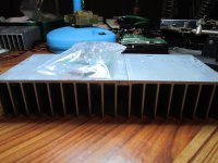
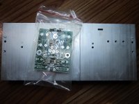
The heatsink is probably just a bit smaller than the 0.5C/watt that LC recommended, but about the same size as my two heatsinks (~25 cm x 10 cm base, with 26 2.5 cm fins). My heatsinks get only moderately warm in normal use. Do you have one heatsink per module, or just one for both modules?I am starting the assembly.
Is this heatsink suitable ? see pictures
It is 21cm w and 9 cm depth and the fin is 4cm in height,
The back plate 3mm thickness.
transformer 0 and 35 V ac x2--300 w
intended application : speaker is 89db/w . room about 2000 cu ft. aiming for 105db peak.
thanks
kp93300
However, that transformer will produce a higher voltage than the +/-45V maximum listed in LC's documentation. Assuming a conventional power supply with a rectifier bridge and caps, the DC voltage will be around +/-49V, plus about 5% at low load., so perhaps up to 51V, not taking line (mains) conditions into account.
Calculated as follows:
35AC * SQRT(2) - 1 diode drop x 1.05 load regulation ~ 51VDC
5% is from the published load regulation of my 330VA transformer, at 60Hz and 115VAC mains voltage (you may want to look up the correct number for 220V/50Hz). If your mains voltage is on the high side (like mine for example), then you have to add another 1-2V to the result.
I am not sure exceeding 45V by that much is a good idea, but perhaps someone else has a more definitive answer on that. In any case, I would make sure ahead of trying it.
A possible solution might be using a different pair of input transistors, instead of the BC550/560 which shipped with the modules.
.....transformer 0 and 35 V ac x2--300 w.....
kp93300
Be aware if following BOM that C14/15/20/21 is only 50V, could be explosive......I am not sure exceeding 45V by that much is a good idea, but perhaps someone else has a more definitive answer on that. In any case, I would make sure ahead of trying it.
A possible solution might be using a different pair of input transistors, instead of the BC550/560 which shipped with the modules.
Good point about the capacitor rating, but with respect, not explosive, I don't think so.Be aware if following BOM that C14/15/20/21 is only 50V, could be explosive.
Not in the case of any modern capacitor. I believe that the rated voltage would have to be exceeded by a much larger percentage to cause "catastrophic" failure, let alone an actual explosion. The most likely result is a shorter than rated life.
Okay things maybe happened in that area, but in my schooltime aprox some 35 years ago teacher demonstrated few overvolt made cap explode, it took time but did explode. 😱Good point about the capacitor rating, but with respect, not explosive, I don't think so.
Not in the case of any modern capacitor. I believe that the rated voltage would have to be exceeded by a much larger percentage to cause "catastrophic" failure, let alone an actual explosion. The most likely result is a shorter than rated life.
Either way, whether it goes with a bang or whimper, do we agree that for this and other reasons, a transformer secondary voltage rating of 35V will be too high, or am I missing something else?Okay things maybe happened in that area, but in my schooltime aprox some 35 years ago teacher demonstrated few overvolt made cap explode, it took time but did explode. 😱
Yes, we agree. I run mine at 30v ac and feel that this is pushing it to the limit, especially with speakers that dip below 8ohms.
No, you are quit right Pete.Either way, whether it goes with a bang or whimper, do we agree that for this and other reasons, a transformer secondary voltage rating of 35V will be too high, or am I missing something else?
 (But if he has or borrow a autotransformer or variotransformer in front to take out the last killing voltage, then he can go with that untill he gets new hardware
  ).
).
Last edited:
Dunno what the variac would add to the sound. Probably nothing good.
A toroid is generally easy to adjust within a small range by either adding to the primary or subtracting from the secondary. Or adding to the secondary but in reverse phase.
A toroid is generally easy to adjust within a small range by either adding to the primary or subtracting from the secondary. Or adding to the secondary but in reverse phase.
+1Use a series-pass regulator configured as a capacitance multiplier and you are good to go.
Maybe you think of some newer modern stuff with electronic swithcing, it is not what i think of, the one i call variotransformer and have myself is old mecanical like wirewound potentiometers just very big and heavy. I am pretty sure it is same wave swings (50Hz this country) comming out (just regulated up/Down by user) as comming out of wall connector power line. My sugestion was also only ment to be temporary for getting up and running until right bits and pieces are in house.Dunno what the variac would add to the sound. Probably nothing good.
A toroid is generally easy to adjust within a small range by either adding to the primary or subtracting from the secondary. Or adding to the secondary but in reverse phase.
You mention adjusting a toroid easy by adding/subtracting for primary/secondary, i am curious can you explain for learning.
Member "Samuel Jayaraj" sugestion going with use of CM i think is smart and will make solution not only temporary.
- Home
- Vendor's Bazaar
- VSSA Lateral MosFet Amplifier