ok so the only way to know for sure is to put a working model on a scope......are you going to build one?But in reality it can oscillate eventhough I have added caps.
So, SPICE is not to be trusted 100%.
The 22pF caps can be needed to increase.
when i built this circuit, i found a minimum of 33pF was needed for stable operation.
peeceebee v4 distortion simulation
peeceebee v4 distortion simulation
Do you thınk 22pf must be 33 or 47? I have took order 33p and 47p now. I will tested.when i built this circuit, i found a minimum of 33pF was needed for stable operation.
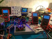
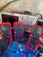
My VSSA works like this in reality. CSS:113mV BIAS:192mA OFFSET:27mV
but I'm still curious about the effect of replacing 22pf with 33pf on the sound.? do I should to try it? What has it advantage?

but I'm still curious about the effect of replacing 22pf with 33pf on the sound.? do I should to try it? What has it advantage?
Attachments
Last edited:
to get offset closer to 0mV, make a small adjustment to either ccs.
with single die pair use around 110mA bias.
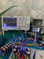
did you check stability? remove C1 and use a 10KHz squarewave signal to give 1Vp-p at the amplifiers output.
with single die pair use around 110mA bias.
did you check stability? remove C1 and use a 10KHz squarewave signal to give 1Vp-p at the amplifiers output.
Last edited:
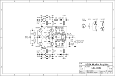
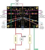
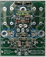
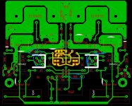
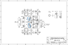
As you can see, my VSSA circuit is set up in this way.
I calculated E= 0.0024x47= 0.113V (113mV) by using the formula E=IxR to set the css set to 2.4mA by sticking to Lazycat's project. I set the current on the positive supply line to 192mA. You can see it in the video. I couldn't set my amp according to vssa's original manual...
In my real time measurements (same connections with simulation); CSS:113mV, +V current:192mA, offset:27mV
In the simulation there are quite different value for offset...
Could you please tell me how to make the exact measurements of the VSSA?
****My 2nd question is what is the effect of changing the 22pf high frequency compensation capacitor to 33pf or 47pf on the sound?
Attachments
Last edited:
The measurement I'm aiming for is exactly like the simulation.
But in real time measurements, for VAS 120mV, CCS 107mV -105mV. this means a CCS less than 2.4mA.
When I make CCS 113mV (47ohmx2.4ma=113mV), VAS becomes 190mV.
When I did all the measurements and removed the 22 ohm resistors and ran it again, I got 182mA bias 120mV VAS in a stable way as it says in the VSSA document. but I got a low CCS of 2.4 mA.
How can I solve this problem?
Attachments

Last edited:
forget simulation.
connect a meter to one of vas 10R
connect another to output (offset)
increase both input currents until the vas 10R has about 100mv (10mA)
next adjust just one of the input current so offset is <10mV
last, set fet bias to 110mA
connect a meter to one of vas 10R
connect another to output (offset)
increase both input currents until the vas 10R has about 100mv (10mA)
next adjust just one of the input current so offset is <10mV
last, set fet bias to 110mA


Hello, dear friends;
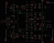
I am here with new details about VSSA. In my examinations, I noticed that lazycat made a change in the VAS compensation capacitor. I also observed this situation in @Nikos's pcbs? What is the purpose of the 22pf and specified in the original schematic and the 5.6pf and 100pf modification made by lazycat and nikos? What is the effect on the sound?

I am here with new details about VSSA. In my examinations, I noticed that lazycat made a change in the VAS compensation capacitor. I also observed this situation in @Nikos's pcbs? What is the purpose of the 22pf and specified in the original schematic and the 5.6pf and 100pf modification made by lazycat and nikos? What is the effect on the sound?
Attachments
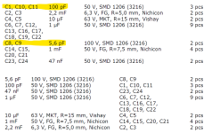
I don't know why this change is made in VSSA and what it provides.
*These diameters are for high frequency compensation; they reduce THD and increase SNR. If you use too much capacity, it reduces high frequency sensitivity and narrows the bandwidth. *
The advantage of this change should be explained to us by diyaudio members who are experienced in VSSA.
*These diameters are for high frequency compensation; they reduce THD and increase SNR. If you use too much capacity, it reduces high frequency sensitivity and narrows the bandwidth. *
The advantage of this change should be explained to us by diyaudio members who are experienced in VSSA.
New PCB is Ready. You can try with 5,6pf or 22pf. New caps KEMET C7, C8 are5,6pf C0G and C17, C18 are100pf.

Yes I finally solved my problems. Very stable amp. 😎
- first you check your amp at sinus and with resistive load 8R.
- then you try some other measurements with bigger current, more input/output power.
- then use 100nF and maybe more of a non polarized cap in parallel to the resistor. and switch your fg to square wave. then you can see ringing or not. the amp is stable or not...
I did test 1. and 2. it is ok.
- first you check your amp at sinus and with resistive load 8R.
- then you try some other measurements with bigger current, more input/output power.
- then use 100nF and maybe more of a non polarized cap in parallel to the resistor. and switch your fg to square wave. then you can see ringing or not. the amp is stable or not...

i am not the expert. so if you have some oscillation post it here with your scope measurements.I did test 1. and 2. it is ok.
- Home
- Amplifiers
- Solid State
- VSSA Lateral Mosfet Amplifier (lazycat) with EXICON