Re: post 76
That's an overheating emergency shutdown. The relay is NC and when it's energized (by a protection logic that senses overheating) it opens and shuts down the whole amp. It acts like the overcurrent protection, but it is non-latching. The hysteresis (to avoid relay "chatting") is provided by the thermal sensor circuitry. It can also be used for other emergency shutdown conditions (low speed) by OR-ing the sensors outputs.
atiq19 said:How does U6 (SPDT) work?
That's an overheating emergency shutdown. The relay is NC and when it's energized (by a protection logic that senses overheating) it opens and shuts down the whole amp. It acts like the overcurrent protection, but it is non-latching. The hysteresis (to avoid relay "chatting") is provided by the thermal sensor circuitry. It can also be used for other emergency shutdown conditions (low speed) by OR-ing the sensors outputs.
Ovidiu,
The realy is Normaly Closed (NC), but during an event of overheating it opens and triggers the switch ''off''. What is the threshold of this overheating temperature. What is acting (sampling) as the thermal transducer? Thermal signal will be anlogue and sampling will incorporate error...there is a question of sensityvity.
Can I omit overheat protection?
Cheers.
Atiq
atiq19 said:Ovidiu,
The realy is Normaly Closed (NC), but during an event of overheating it opens and triggers the switch ''off''. What is the threshold of this overheating temperature. What is acting (sampling) as the thermal transducer? Thermal signal will be anlogue and sampling will incorporate error...there is a question of sensityvity.
Can I omit overheat protection?
Cheers.
Atiq
http://synaesthesia.ca/Prot-Sch.html in the upper left corner, MAX6665ASA55. Also controls a fan, see the Maxim datasheet.
If you don't want the overheating protection, just replace the relay with a wire 😀

post 84
Hi Ovidiu,
Now I see the whole picture.
Without any detail set-up/calibration instruction it will be challenging to set up the whole controller for a beginner like me.
Anyway, if you do not wish to publish any public building instructions I wouldn't be building that thermal housekeeping controller.
Thanks for sharing.
Atiq
Re: post 84
There's nothing to calibrate. The Maxim chip has the two temperature limits (start fan and shutdown) hardwired, so the only issue is installing the litle board with the SOT8 chip in thermal contact with the heatsink.
I'm still trying to decide between a bipolar or MOSFET output versions, certainly construction details will follow ASAP.
atiq19 said:Hi Ovidiu,
Now I see the whole picture.
Without any detail set-up/calibration instruction it will be challenging to set up the whole controller for a beginner like me.
Anyway, if you do not wish to publish any public building instructions I wouldn't be building that thermal housekeeping controller.
There's nothing to calibrate. The Maxim chip has the two temperature limits (start fan and shutdown) hardwired, so the only issue is installing the litle board with the SOT8 chip in thermal contact with the heatsink.
I'm still trying to decide between a bipolar or MOSFET output versions, certainly construction details will follow ASAP.
atiq19 said:Ovidiu,
I am wondering whether adding some off the shelf regulators add any value to the LME49710 op amp?
Do we achieve any improvement if we run OPS so called non-switching?
Thanks for answering.
Atiq
No, a zener is all you need.
The OPS is already non-switching (in the Self sense) and anyway, distortions are in the low ppm range, so I don't think anything else is really required. The only serious problem I'm contemplating is to find a way to measure the transient thermal response of the OPS.
Hi Ovidiu,
Did you consider cfp OPS, with driver transistor TT only. We may reduce number of TT devices in this way...perhaps better transient behaviour.
Do you wish to elaborate Self's non switching defination?
Cheers.
Atiq
Courtesy: Abomination thread by MJL
Did you consider cfp OPS, with driver transistor TT only. We may reduce number of TT devices in this way...perhaps better transient behaviour.
Do you wish to elaborate Self's non switching defination?
Cheers.
Atiq
Courtesy: Abomination thread by MJL
Attachments

I went to maxim.com to look up that datasheet, but the site wasn't what I expected 😀. It should be maxim-ic.com.
post 76
Is R59 (100K) correct value? Was much lower before.
How does the TT bias spreader maintain tracking sensityvity more than unity? It has been found in the TT Thread that tracking sensityvity has to be much more than unity before gaining any sensible benefit with these ONSemi power transistors.
Is R59 (100K) correct value? Was much lower before.
How does the TT bias spreader maintain tracking sensityvity more than unity? It has been found in the TT Thread that tracking sensityvity has to be much more than unity before gaining any sensible benefit with these ONSemi power transistors.
Re: post 76
R59 is correct at 100k. TL431 are now used as references, 1mA is more than enough. Previously I used low voltage zenners which need much more current. C8/R9 are both compensating the overcurrent loop and providing reference decoupling, without affecting the TL431 poor stability with capacitive loads.
For the second question, I don't know. The output stage thermal loop is a straight Bob Cordell design (published on this forum) and I can tell it works perfectly fine, statically. I'm still trying to figure out if this is an optimal solution. The Onsemi models for TT devices, MUR 120, MJL4281, etc... are all far off.
atiq19 said:Is R59 (100K) correct value? Was much lower before.
How does the TT bias spreader maintain tracking sensityvity more than unity? It has been found in the TT Thread that tracking sensityvity has to be much more than unity before gaining any sensible benefit with these ONSemi power transistors.
R59 is correct at 100k. TL431 are now used as references, 1mA is more than enough. Previously I used low voltage zenners which need much more current. C8/R9 are both compensating the overcurrent loop and providing reference decoupling, without affecting the TL431 poor stability with capacitive loads.
For the second question, I don't know. The output stage thermal loop is a straight Bob Cordell design (published on this forum) and I can tell it works perfectly fine, statically. I'm still trying to figure out if this is an optimal solution. The Onsemi models for TT devices, MUR 120, MJL4281, etc... are all far off.
Re: Re: post 76
Hi syn08, good to see that you are back after your holyday 😀
Onsemi model:
Agree, and that is the pain in the ***, have a look at the measurements done by John Gedde.
Thermal loop:
Also remember that the TT diodes only relates to the output transistors (2xVbe), that is why I like the latest Vbe spreader by Bob better.
syn08 said:
For the second question, I don't know. The output stage thermal loop is a straight Bob Cordell design (published on this forum) and I can tell it works perfectly fine, statically. I'm still trying to figure out if this is an optimal solution. The Onsemi models for TT devices, MUR 120, MJL4281, etc... are all far off.
Hi syn08, good to see that you are back after your holyday 😀
Onsemi model:
Agree, and that is the pain in the ***, have a look at the measurements done by John Gedde.
Thermal loop:
Also remember that the TT diodes only relates to the output transistors (2xVbe), that is why I like the latest Vbe spreader by Bob better.
Re: Re: Re: post 76
Actually my vacation was only over the weekend. It was since reconsidered by Gods and they decided I don't really deserve one.
I still need to take the time and figure out (in isolation) which loop is better.
stinius said:
Hi syn08, good to see that you are back after your holyday 😀
Onsemi model:
Agree, and that is the pain in the ***, have a look at the measurements done by John Gedde.
Thermal loop:
Also remember that the TT diodes only relates to the output transistors (2xVbe), that is why I like the latest Vbe spreader by Bob better.
Actually my vacation was only over the weekend. It was since reconsidered by Gods and they decided I don't really deserve one.
I still need to take the time and figure out (in isolation) which loop is better.
Hi syn08
What is the progress regarding this amp?
BTW the amp I told you about by e-mail simulates really nice in OrCAD.
Cheers
What is the progress regarding this amp?
BTW the amp I told you about by e-mail simulates really nice in OrCAD.
Cheers
stinius said:Hi syn08
What is the progress regarding this amp?
BTW the amp I told you about by e-mail simulates really nice in OrCAD.
Waiting in the PCB queue. I decided for the bipolar version (4 pairs NJL per channel), it is my first adventure there in the last years.
The OPS posted above measures (with only two pairs on the breadboard, fan cooled) 0.08% THD20 open loop @ 80Vpp into 4 ohm, that is about 200W, not bad at all. Compared to the original Bob Cordell's version, there's a slight change in the thermal compensation (another diode in the loop, the original was undercompensated) and in the driver bias, I'll be back with the full schematics.
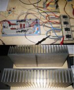
Monster heatsinks from ro-theta are already in, see the picture.
I think I'll get addicted to bipolars 🙂
Attachments
VSOP release
Done guys, this is the VSOP 1.1.3 release.
The board level schematic is attached. Don't be scared by the apparent complexity; in fact, the signal path is ridiculously simple.
A triple EF bipolar output stage, with four pairs of Thermaltrak devices. Thermal compensation is based on a Bob Cordell idea, modified/optimized for pretty much zero coefficient. After several hours of 400W into 4 ohm, the bias was down 5mA from the original 4 x 120mA. For clarity, I'll also post below a schematic of the output stage only.
A folded cascode VAS, running at 5mA, TPC compensated for a unity gain frequency of about 4MHz and a phase marging of 75 degrees.
A current feedback input stage in non-inverting configuration, with local feedback for a gain of 11.
An opamp input stage providing the rest of the gain to 28dB, set by a global feedback loop. The overall unity gain frequency is about 3.5MHz and the phase marging is about 85 degrees.
The rest (60%) are "frills", though required for such a high power construction. Current protection around my "audio thyristor" (Q15/Q16) as in the YAP amp, an active clamp (Q11/Q19) as I showed previously in this thread (with an additional diode to increase the margin, as Glen suggested), and emergency shut down (the relay) activated by the power sequencing, thermal protection and other critical condition sensors (TBD, on a separate board, using the same kind of "analog computer logic" as in the PGP amp), a servo for almost zero output offset (although using a low offset opamp makes this really a "frill").
Quick measurements shows 15-20ppm THD20 at 400W into 4 ohm. At 100W into 8 ohm, distortions are close to the 1ppm barrier (haven't had yet the time to get a reliable number).
120V/uS slew rate, stable in any load I was able to simulate (including a 2uF with 1 ohm in series). BTW, anybody ever seen a 2.2uF film cap exploding? It's nowhere less spectacular (and dangerous) then a large electrolytic reverse biased 🙁
The input cap defines the closed loop bandwidth and smooths any overshoots in the transient response (inherent in TPC) to a RC low pass response.
Here's the output stage schematic, shown only for to illustrate the thermal compensation. Note the extra diodes (compared to Bob's original design) and the R270/R271 resistors used to trim the thermal coefficient to almost zero. Reason for all these is that Bob's original design turned out to have a slight positive temperature coefficient, enough though to make the whole OPS thermally unstable at high power.
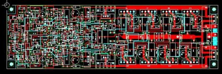
Here's the full amp board level schematic:
The PCB layout picture is attached. The board is 10" x 3" double sided and screws directly on a R-theta heatsink I have posted the picture above.
I'll be back with pictures of the construction and more measurements. Gerber downloads etc... will be available soon on my web site.
Have mercy, this is my first fully bipolar high power amp 🙂 How does it sound? Don't know for sure yet, but certainly not worse than the PGP and YAP. It is though different.
Done guys, this is the VSOP 1.1.3 release.
The board level schematic is attached. Don't be scared by the apparent complexity; in fact, the signal path is ridiculously simple.
A triple EF bipolar output stage, with four pairs of Thermaltrak devices. Thermal compensation is based on a Bob Cordell idea, modified/optimized for pretty much zero coefficient. After several hours of 400W into 4 ohm, the bias was down 5mA from the original 4 x 120mA. For clarity, I'll also post below a schematic of the output stage only.
A folded cascode VAS, running at 5mA, TPC compensated for a unity gain frequency of about 4MHz and a phase marging of 75 degrees.
A current feedback input stage in non-inverting configuration, with local feedback for a gain of 11.
An opamp input stage providing the rest of the gain to 28dB, set by a global feedback loop. The overall unity gain frequency is about 3.5MHz and the phase marging is about 85 degrees.
The rest (60%) are "frills", though required for such a high power construction. Current protection around my "audio thyristor" (Q15/Q16) as in the YAP amp, an active clamp (Q11/Q19) as I showed previously in this thread (with an additional diode to increase the margin, as Glen suggested), and emergency shut down (the relay) activated by the power sequencing, thermal protection and other critical condition sensors (TBD, on a separate board, using the same kind of "analog computer logic" as in the PGP amp), a servo for almost zero output offset (although using a low offset opamp makes this really a "frill").
Quick measurements shows 15-20ppm THD20 at 400W into 4 ohm. At 100W into 8 ohm, distortions are close to the 1ppm barrier (haven't had yet the time to get a reliable number).
120V/uS slew rate, stable in any load I was able to simulate (including a 2uF with 1 ohm in series). BTW, anybody ever seen a 2.2uF film cap exploding? It's nowhere less spectacular (and dangerous) then a large electrolytic reverse biased 🙁
The input cap defines the closed loop bandwidth and smooths any overshoots in the transient response (inherent in TPC) to a RC low pass response.
Here's the output stage schematic, shown only for to illustrate the thermal compensation. Note the extra diodes (compared to Bob's original design) and the R270/R271 resistors used to trim the thermal coefficient to almost zero. Reason for all these is that Bob's original design turned out to have a slight positive temperature coefficient, enough though to make the whole OPS thermally unstable at high power.
An externally hosted image should be here but it was not working when we last tested it.
Here's the full amp board level schematic:
An externally hosted image should be here but it was not working when we last tested it.
The PCB layout picture is attached. The board is 10" x 3" double sided and screws directly on a R-theta heatsink I have posted the picture above.
I'll be back with pictures of the construction and more measurements. Gerber downloads etc... will be available soon on my web site.
Have mercy, this is my first fully bipolar high power amp 🙂 How does it sound? Don't know for sure yet, but certainly not worse than the PGP and YAP. It is though different.
Attachments
Congratulations to another fine amp that you are building!
Now that's really a surprise for everybody that judges an amp on THD only.
Have fun, Hannes
PS: by the way I envy you for your building speed, the 2nd channel of my amp is now sitting unmarrily for more than one week already waiting to be finished (the whole amp was certainly started before your last version was even final) and I have already all parts at hand.
It is though different.
Now that's really a surprise for everybody that judges an amp on THD only.
Have fun, Hannes
PS: by the way I envy you for your building speed, the 2nd channel of my amp is now sitting unmarrily for more than one week already waiting to be finished (the whole amp was certainly started before your last version was even final) and I have already all parts at hand.
- Status
- Not open for further replies.
- Home
- Amplifiers
- Solid State
- VSOP amp