Series R with comp cap usually helps with oscillation, and 1R does almost nothing to performance but might help a lot with oscillations.
What output capacitor is used?
edit: also you can go 33n/47n even for comp cap.
There's a zone between working fine and oscillating where it's somewhat stable but with higher noise floor. I think the negative regulator might be in this area atm.
Also replace the output cap just for testing with the 470uF Panasonic FR cap.
Last edited:
I feel confident these measurements are correct. I changed to 48k sampling, set high and low pass filters to 10Hz and 30kHz, and adjusted graph settings.
Calibration using 4uV/rtHz method
View attachment 923886
Negative Rail
View attachment 923887
Positive Rail
View attachment 923888
Looking at these photos the PSRR between the rails seems to be the same. That is a change since the first you measured them.
edit: ah no, it's not a dB measurement.
Got the transformer cooled down and it is fine. Here is the negative rail with the ESR Resistor on the output cap replaced with a wire. Also, I currently have a 30nF + 1 ohm resistor installed on both rails. I had read that somewhere in the thread when they had issues with the TI regulators.
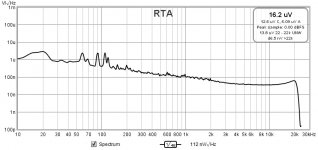
This change made it way more jittery jumps all over even when touching the PC keyboard.
Will work on this more tomorrow.

This change made it way more jittery jumps all over even when touching the PC keyboard.
Will work on this more tomorrow.
A few posts back I put measurements for LM337 from TI, with denoiser and also dienoiser.
It's possible the TI LM337 is not as immune to other issues like other LM337s made by other manufacturers.
It's possible the TI LM337 is not as immune to other issues like other LM337s made by other manufacturers.
I feel confident these measurements are correct. I changed to 48k sampling, set high and low pass filters to 10Hz and 30kHz, and adjusted graph settings.
I checked some noise measurements that I have made earlier. It seems your negative rail has about the same noise that I had with LM317+Cadj (i.e. without denoiser) although in my test the output voltage was only 7V. So maybe you should check the PNP transistor (BC327) as well. It may also be useful if you could repeat the noise measurement but with denoiser bypassed.
I don't see the ESR for the first capacitor in the BOM, but the second one has a ESR of 0.121R. If I try to extract the ESR of the first option for output cap, based on the tan value, I get somewhere between 70 and 80mOhm. Which is higher than all that worked for me.
If you have any extra Panasonic FR 470uF/25V use it on the negative rail output, and don't change the compensation network, leave it as it is now.
If you have any extra Panasonic FR 470uF/25V use it on the negative rail output, and don't change the compensation network, leave it as it is now.
The picture above was not correct, seems like I say that a lot. Something locked up in REW. I noticed after I disconnected the input lead and the display stayed the same. So rebooted and it is working correctly. I now trust the graphs below.
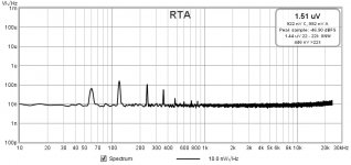
VRDN Negative Rail with .47 ESR adjusting resistor and 2200uF in place
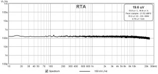
VRDN negative rail with .47 ESR resistor replaced with wire, 2200uF in place
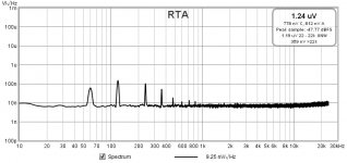
VRDN negative rail with .47 ESR resistor replaced with wire and 2200uF cap replaced with Panasonic Series FR 470uf/25V
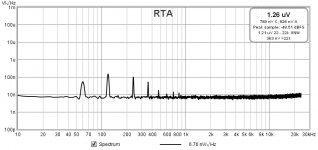
VRDN Negative Rail with .47 ESR adjusting resistor and 2200uF in place

VRDN negative rail with .47 ESR resistor replaced with wire, 2200uF in place

VRDN negative rail with .47 ESR resistor replaced with wire and 2200uF cap replaced with Panasonic Series FR 470uf/25V

Your last 2 graphs seem to be quite alright. Noise is more or less where it should be (below 10nV/rtHz).
The measurement with the 470uF cap (and original BJT) has a lower noisefloor.
Do the PSRR measurement with both original 2200uF cap and 470uF.
Do the PSRR measurement with both original 2200uF cap and 470uF.
Also after the PSRR measurement maybe you can revert the comp network to the recommended values for rev.A2 and measure noise and PSRR again, so people can rely on the recommendations for that revision. At the moment your compensation network is different from the rev.A2 values.
BTW, the graphs can be a little misleading because the noise does jump up and down just a little, but I agree, the BC327 and 470uF were very slightly lower.
I'm going to order those caps and resistors so I can do that.
For the negative rail you'd only need the 22n cap without a resistor for comp network.
VRDN negative rail with .47 ESR resistor replaced with wire, 2200uF in place

- Home
- Amplifiers
- Power Supplies
- VRDN: bipolar regulator PCB for line level ckts: ±11V to ±20V @ 1.5A with "De-Noiser"
