Please, take my comments lightly, as they are based on a comparison simulation I made between the VRDN and the original Denoizator.
I had to load the VRDN schematic on LTSpice, as I found none .asc here. So I am enclosing they both for anyone to verify my findings.
What I did was simulate psrr, noise and impedance, and the results were practically the same in both designs.
Except my design had a simple RC filter at the input, and the VRDN is "covered" by 2200uF caps which didn't influence the results. Perhaps they measure different from the simulation? Some people say simulations should be considered not too reliable. Others say they should.
The larger output capacitor didn't make any difference in psrr sim on the original or on the VRDN, and both remained the same at -32dB.
So I wonder why use so many caps? Did the audio unit you powered with the multiple capacitors sound better than the one with a single cap?
I can upload all the other sims if you want to.
Attachments
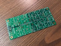
I was very nice surprised when I found this thread. I have a similar design myself which works great, but this seems also very nice. So I decided to try it out. Might use it for my dual 19" channelstrip (pre-amp, compressor, EQ) that I am building. Boards are in, parts are in. I ordered green soldermask with ENIG finish. And off course have some boards left, so if anyone wants just 1 board, DM me (I'm from The Netherlands).
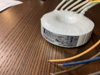
BTW. Using a 50VA, dual secondary 18V transformer, May be a bit overkill, but I got a good deal on it 🙂 Some pics pre-stuffing included.
BTW. Using a 50VA, dual secondary 18V transformer, May be a bit overkill, but I got a good deal on it 🙂 Some pics pre-stuffing included.
Attachments

If you're planning to use VRDN to deliver regulated DC to quite a few different boards, I recommend you start thinking about your output wiring, right now. There are only eight "Euroblox" screw terminals on the DC outputs of VRDN (2xVplus , 2xVminus , 4xGround) and that might not be enough for your needs, with all the boards you plan to connect.
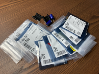
One possible approach seems to be widespread in Europe but not too common in the U.S.: wire ferrules. These let you crimp two, or even three, stranded wires into a single ferrule pin, which is inserted into the Euroblox screw terminal. I bought this kit on Amazon and liked it so well, I bought a second complete kit and gifted it to our esteemed Moderator, @6L6 . He liked it too.
One possible approach seems to be widespread in Europe but not too common in the U.S.: wire ferrules. These let you crimp two, or even three, stranded wires into a single ferrule pin, which is inserted into the Euroblox screw terminal. I bought this kit on Amazon and liked it so well, I bought a second complete kit and gifted it to our esteemed Moderator, @6L6 . He liked it too.
The ferrules are one of those things I never knew I needed, and now never want to be without. Highly recommended.

Don't worry. On all the boards I have a "Power through" connector. So I can daisy chain the power as well as the single. 🙂If you're planning to use VRDN to deliver regulated DC to quite a few different boards, I recommend you start thinking about your output wiring, right now. There are only eight "Euroblox" screw terminals on the DC outputs of VRDN (2xVplus , 2xVminus , 4xGround) and that might not be enough for your needs, with all the boards you plan to connect.
And I always use ferrules with screw terminals. I rarely connect multi-stranded wires to a screw terminal.
New possible group buy thread started. Please see this thread:
https://www.diyaudio.com/community/threads/potential-group-buy-for-vrdn-boards.395582/
https://www.diyaudio.com/community/threads/potential-group-buy-for-vrdn-boards.395582/
Thanks for bringing this my attention. Like 6L6, I never thought I needed a tool like this. The order is placed. 🙂If you're planning to use VRDN to deliver regulated DC to quite a few different boards, I recommend you start thinking about your output wiring, right now. There are only eight "Euroblox" screw terminals on the DC outputs of VRDN (2xVplus , 2xVminus , 4xGround) and that might not be enough for your needs, with all the boards you plan to connect.
One possible approach seems to be widespread in Europe but not too common in the U.S.: wire ferrules. These let you crimp two, or even three, stranded wires into a single ferrule pin, which is inserted into the Euroblox screw terminal. I bought this kit on Amazon and liked it so well, I bought a second complete kit and gifted it to our esteemed Moderator, @6L6 . He liked it too.
Hoping to get some help on my VRDN. I bought two of these boards to try in a dual mono for Waynes Preamp.
First board fired up fine with voltages dialed in right at +-15 on both sides.
The second board V- is giving me some problems. I can get the V+ to 15V and even higher to 21V, but the (-) can only reach up to -14.68V.
I checked every diode orientation and confirmed my resistors were correct. Voltages out of the regulator appear to be fine, but it feels like the divider with the trimmer pot has some issues around it.
I re-flowed all solder joints on that side of the board as well as pulling the 2K trim pot to test it..
Any other ideas as to why I cannot adjust V- any higher?
I used the EXACT parts list on here with the exception of the 220 ohm resistor but I used the same one on both boards.
Quick update.
- Q2 BC327
No luck getting higher than -14.81V. Any other ideas on which parts to focus on?
- I brushed the bottom of the board real good with 99% isopropyl alcohol
- Removed and tested the below components:
- Q2 BC327
No luck getting higher than -14.81V. Any other ideas on which parts to focus on?
The reason why these six resistors are marked "1%" on the schematic, is because the VRDN circuit design requires a tolerance of 1% or better for each of them. If these six resistors on your board, are not 1% tolerance (guaranteed by the resistor manufacturer), replace them.
_
_
Attachments
Thanks Mark.
The resistors I used were the exact ones from the parts list with the exception of R12 which is an RN55 vishay/Dale.
I’ll go ahead and check them just to be sure.
The resistors I used were the exact ones from the parts list with the exception of R12 which is an RN55 vishay/Dale.
I’ll go ahead and check them just to be sure.
Either (a) the LM337's input is correct but its output is wrong; or else (b) the LM337's input is wrong so naturally its output is wrong too.
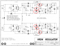
To understand better, measure these three node voltages (with respect to ground), then copy them onto the attached image file and post the annotated image file here. Measure with the De-Noiser jumpers removed, then just for giggles, measure again with the De-Noiser jumpers installed. In a correctly functioning board there "should be" no difference at all. Especially if the LM337 was manufactured by OnSemi.
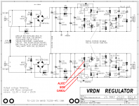
If you stuffed D1, R9, R10, and R12 following the silkscreen hints on the VRDN PCB, ALICE should be on the flying wirelead of R9. Bob should be on the flying wirelead of R12. Carol should be on the flying wirelead (anode) of D1.
_
To understand better, measure these three node voltages (with respect to ground), then copy them onto the attached image file and post the annotated image file here. Measure with the De-Noiser jumpers removed, then just for giggles, measure again with the De-Noiser jumpers installed. In a correctly functioning board there "should be" no difference at all. Especially if the LM337 was manufactured by OnSemi.
If you stuffed D1, R9, R10, and R12 following the silkscreen hints on the VRDN PCB, ALICE should be on the flying wirelead of R9. Bob should be on the flying wirelead of R12. Carol should be on the flying wirelead (anode) of D1.
_
Attachments

Last edited:
Awesome. I’ll check these voltages when I get home.
I forgot to mention, the On Semi’s were out of stock from mouser so I ordered Texas Instruments. Maybe I got a bad LM337.
I purchased two new ones locally from my electronics store to try out.
Before removing I’ll get those voltages.
I forgot to mention, the On Semi’s were out of stock from mouser so I ordered Texas Instruments. Maybe I got a bad LM337.
I purchased two new ones locally from my electronics store to try out.
Before removing I’ll get those voltages.
Below are my measurements at each. Appears my denoiser does not have complete matching voltages
Alice - R9 -6.8V
Bob - R12 -13.72
Carol - D1 Anode -27.53V
With Denoiser
Carol is almost the same
Bob increases to -18.84V
Alice increases to -9.33V
Alice - R9 -6.8V
Bob - R12 -13.72
Carol - D1 Anode -27.53V
With Denoiser
Carol is almost the same
Bob increases to -18.84V
Alice increases to -9.33V
... measure these three node voltages (with respect to ground), then copy them onto the attached image file and post the annotated image file here. Measure with the De-Noiser jumpers removed, then just for giggles, measure again with the De-Noiser jumpers installed.
1. where's your annotated image file?
2. When you write "With Denoiser" do you actually mean "With Jumper installed" (which, in fact, disables the denoiser)?
Sorry. I got in a rush when I got home. About to bath baby and get her to bed. I’ll add that image. With voltages right after.
First voltages (without jumper)
Second voltages (with jumper)
Sorry I got that mixed up.
First voltages (without jumper)
Second voltages (with jumper)
Sorry I got that mixed up.
@Mark Johnson are you an instructor? Just wondering, your asking the same types of questions I use quite a lot. I teach automotive classes.
New update... I swapped in one of the regulators I bought from my local electronics store (National brand) and it works fine... Looks like it was just a bad regulator.
Thanks for the help on this
Thanks for the help on this
@Mark Johnson are you an instructor? Just wondering, your asking the same types of questions I use quite a lot. I teach automotive classes.

Best,
Anand.
- Home
- Amplifiers
- Power Supplies
- VRDN: bipolar regulator PCB for line level ckts: ±11V to ±20V @ 1.5A with "De-Noiser"