It sounds to me like there's probably a short circuit between the negative unregulated supply and ground. Either in one of the negative filter capacitors C4, C6, C8, C10, C12, or else in the negative regulator IC LM337 itself.
If you've got a way to run the board for minutes at a time without destroying another AC-to-AC wall wart, I suggest you unsolder and remove those caps one by one. Power up after each unsoldering and determine: did the short disappear? Leave C12 for last. If there's still a short with only C12 and the LM337, remove the LM337 (leaving C12 installed) and test. You can do this by cutting the pins of the TO-220 and then unbolting it from the heatsink. Next unsolder the remaining stumps of the cut-off pins.
If you don't have a way to electrically test the board without possibly damaging your wall wart, I suggest you unsolder all five caps and also remove the LM337. Check with your ohmmeter to see if there's still a short. Reverse the probes and check again. You won't know which component went bad, but you will know the failed part is in the trash can and not on your PCB.
All of this unsoldering work is potentially risky, you might accidentally lift off a copper pad, or cut a trace, or burn up an adjacent component. There is a chance you might be forced to start over with a fresh bare board and brand new components. If that happens I recommend you build the complete negative regulator half of the board first and verify that it works. Sweet Victory! Persistence, hard work, and stubbornness have carried the day. Then build the positive half and enjoy the music.
_
Last edited:
I can attest to the difficulty of unsoldering on this board. Solder wick works very well and I found sometimes it works better to add more solder to the joint, then hit is with the wick. I also turned my iron up to about 400C, that increases the risk of lift and burning.
Thanks Mark. I hadn't thought about that approach to troubleshooting the problem and I am going to give that a try.
If you get to the point you think you have it figured, and don't have the resistors to make a load for the wall wart, you could always fuse it, so it will take out the fuse instead of the supply.... just sayn. 🙂
A possible workaround is to use a variant of the light bulb tester: use an automotive 12V or 24V traditional bulb in series with the AC source.
It could be a 5W, 15W or even 21W when you feel confident enough.
In the meantime, you'll be able to make tests and measurements with a relative peace of mind
It could be a 5W, 15W or even 21W when you feel confident enough.
In the meantime, you'll be able to make tests and measurements with a relative peace of mind
Thanks to all of you for the suggestions. I followed Mark's advice and got lucky because the first capacitor I pulled was C10 and that turned out to be the cause of the short in the board. As soon as C10 was removed I was able to measure -15 V at the output. After replacing C10 and removing the Dim Bulb Tester and 100 Ohm resistor (better safe than sorry) I was able to adjust the pots to give me exactly 18 volts on both the positive and negative rails! Now my next step will be to see if I can get the VRDN working with the Wayne's BA2018 boards I have built.
Thanks again for all the help and support!
Thanks again for all the help and support!
Hallelujah!! It's fantastic to hear that you've got it up and running. A nice bit of luck that you only had to replace one component to get er workin.
Well done and good on ya.
Well done and good on ya.
Does anyone have two boards they would like to sell? I don't mind sending it to a fab, but I figured I would check to see if anyone has extra first.
Does anyone have two boards they would like to sell? I don't mind sending it to a fab, but I figured I would check to see if anyone has extra first.
Although those ARE printed circuit boards, and they ARE in stock, ....They are in stock...
Smooth Like Buttah SLB Class A PSU | Etsy
Select white
they are not bipolar voltage regulators, they are not for line level circuits, they do not include "De-Noiser" functionality, and their name is not VRDN.
24V VRDN
I have configured a VRDN to deliver +-24V @ 75mA. The steps I took were:
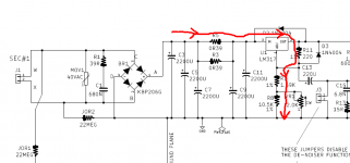
I replaced VR1 and VR2 with 5K trimpots to allow adjustment to +-24V. To test this configuration \, I first ran the regulator with J3 and J4 IN PLACE (disabling the de-noiser function). Everything ran cool with a 330R load on each side.
Then I ran the board with J3 and J4 OUT. All was good. I switched the regulator off. When I started it again some time later, a sharp SNAP indicated a fault - I turned it off. The output of the +ve rail was shorted. I progressively removed components working back from the output. I did not find faulty components. I conclude the fault was in the PCB.
I built a second regulator board following the same procedure. Now the regulator rails settle at +-24V give or take a few millivolts when driving the 2 x 330R load.
Is it regulating and is its stable? Possibly. Comments welcome.
Can VRDN output 24v? For ba3 pre?
I have configured a VRDN to deliver +-24V @ 75mA. The steps I took were:
- Measure the output of the power transformer (2 x 30VAC in my case) and the primary and secondary resistances
- Enter that data into PSUD2 to check the voltages generated in the rectifier and smoothing caps when delivering +-24V into a 2 x 330R load
- Considering the PSUD2 results, keep MOV1 and MOV2 - they will be OK
- Considering the PSUD2 results, replace C3 C4 C5 C6 C7 C8 with 63V caps 16mm diameter and 7.5mm pitch - in my case, these were 1000uF 63V rather than 2200uF 35V
- Considering the PSUD2 results, replace R3 R4 R5 R6 with 2 x 120R 2W dropper resistors, reducing the voltage across the LM317 and LM337 to under 4V
- At 75mA, the heatsinks become optional
- At +-24V, R15 and R16 will dissipate 320mW, over half their rated 600mW which is just OK - replace them with 1W resistors
I replaced VR1 and VR2 with 5K trimpots to allow adjustment to +-24V. To test this configuration \, I first ran the regulator with J3 and J4 IN PLACE (disabling the de-noiser function). Everything ran cool with a 330R load on each side.
Then I ran the board with J3 and J4 OUT. All was good. I switched the regulator off. When I started it again some time later, a sharp SNAP indicated a fault - I turned it off. The output of the +ve rail was shorted. I progressively removed components working back from the output. I did not find faulty components. I conclude the fault was in the PCB.
I built a second regulator board following the same procedure. Now the regulator rails settle at +-24V give or take a few millivolts when driving the 2 x 330R load.
- On start-up with J3 and J4 IN PLACE, the output voltage climbs smoothly to +-24V
- With J3 and J4 OUT and the de-noiser engaged, the output at first overshoots 24V, then undershoots, then rises again, settling after 3 oscilatory cycles
Is it regulating and is its stable? Possibly. Comments welcome.
Last edited:
I have been interested in overdriving the vrdn for a ba-3 pre as well and asked.
Mark and Jim (authors of the VRDN AFAIK) both confirmed it was easy to achieve (by changing some resistors values/relations, AS LONG AS the denoiser-part was omitted.
Your experiments seem to confirm it.
I unfortunately haven’t built it, because I still feel uncomfortable when it comes to alter proven concepts. Although I am confident I (c/w)ould succeed. I am quite a Sissy.
The behaviour is normal for a "standard" denoiser: it is a tradeoff between the VLF correction, the capacitors size and the settling time.[*]With J3 and J4 OUT and the de-noiser engaged, the output at first overshoots 24V, then undershoots, then rises again, settling after 3 oscilatory cycles
[/LIST]
Is it regulating and is its stable? Possibly. Comments welcome.
If you want to shorten the settling time, you have two options: increasing the 220µ cap value will result in more damped response, with a lessened overshoot and a shorter settling time, or decrease the 22µ, which will have a ~similar effect at the expense of the VLF correction.
A 10µ cap will leave the 50/60Hz (and of course 100/120Hz) effectiveness intact
24V VRDN
Thanks Elvee - I will leave this board as it is and consider the 10uF cap if the low frequency settling would be a problem for the downstream circuit.
🙂
Thanks Elvee - I will leave this board as it is and consider the 10uF cap if the low frequency settling would be a problem for the downstream circuit.
🙂
I finally got around to ordering my boards. I have about 15 extra, so if anyone is interested, send me a PM. CONUS only and it takes me a few days to get to the post office.
I'm building my VDRN. I don't see a shunt resistor which would drain the caps when power is off. Has anyone added a shunt resistor? Where/how, and what value (100k, 1M, ??)
Mark certainly knows much more than I do about this stuff, so I'm respectfully wondering why he didn't include one on the board. I think of them as an important safety component for something which might be holding line-level voltage (but I'm still a beginning-level hobbyist at this, and don't even know what I don't know).
Mark certainly knows much more than I do about this stuff, so I'm respectfully wondering why he didn't include one on the board. I think of them as an important safety component for something which might be holding line-level voltage (but I'm still a beginning-level hobbyist at this, and don't even know what I don't know).
VRDN converts AC into DC -- a typical configuration would be 18V AC input and ±15V DC output. The AC comes from the secondary winding(s) of a transformer, which might be an AC wall wart if the builder chooses that option.
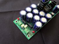
There's no line level voltage anywhere on VRDN ... which is why it uses filter capacitors rated for "only" 35 volts, see attached photo.
When the mains AC applied to the transformer is switched off, VRDN's filter capacitors are discharged through R11-R7-R8, plus the (much smaller) discharge current through R15-Q1. These current paths (a) discharge the output DC voltage all the way to zero; and (b) they also discharge all of the 2200uF/35V electrolytic capacitors to {very roughly} ~~ 2V, before the regulator ICs cease conducting. If you don't want those capacitors sitting around at 2V for a few hours, feel free to add a bleeder resistor in parallel with C11, on the back side of the PCB. A conservative choice would be Rbleeder >= 5.6K with 600mW rating. That way, during normal operation, even if the caps were operating at 34.999 volts, just about ready to explode from overvoltage, the power dissipated in the bleeder resistor would be only (35 * 35 / 5600) = 0.22 watts. Comfortably below the max rated power of the bleeder resistor. You can calculate the timeconstant of the discharge event ... it's a lot quicker than "a few hours".
_
Attachments
- Home
- Amplifiers
- Power Supplies
- VRDN: bipolar regulator PCB for line level ckts: ±11V to ±20V @ 1.5A with "De-Noiser"