Stee,
the 1530 and 214 do not make a good VAS stage.
They are much more suited to the output stage of the discrete opamp if you need to drive ~1k0 loading.
For >5k0 loading stay with the low Cob transistors.
the 1530 and 214 do not make a good VAS stage.
They are much more suited to the output stage of the discrete opamp if you need to drive ~1k0 loading.
For >5k0 loading stay with the low Cob transistors.
respect standard
standard design (OP-Amp and amplifier)
you have unbalanced input
and unbalanced output
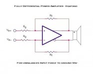
fully differential means (OP-Amp and amplifier)
unbalanced or balanced input
and balanced output
double tension - double dynamic
also have for sure better sound
because bridge compense emphasys of transistors
standard design (OP-Amp and amplifier)
you have unbalanced input
and unbalanced output
fully differential means (OP-Amp and amplifier)
unbalanced or balanced input
and balanced output
double tension - double dynamic
also have for sure better sound
because bridge compense emphasys of transistors
Attachments

Stee,
as a matter of fact, I put my question by mistake. I agree with you, currently building an amp with balanced topology (thanks again for the hint, Klaus).
Extremely nice devices, except 2SK214/2SJ77 are explicitly unsuitable in VAS.
as a matter of fact, I put my question by mistake. I agree with you, currently building an amp with balanced topology (thanks again for the hint, Klaus).
Extremely nice devices, except 2SK214/2SJ77 are explicitly unsuitable in VAS.
Voltage Amplification's Enigma
"Extremely nice devices, except 2SK214/2SJ77 are explicitly unsuitable in VAS"
Hi
normally I see in drawings and use too MJE350/340 for VAS
so this mosfet 2SK214/J77 have the same max current: 500mA
also are very similar to each other (N and P ch)
more then transistors... this is the most critical, at last.
I add that the mosfet are more suited to tension than the current gain
😱
Attachments
Hi
In your lates schematics, it looks like the input jfets are polarised at a relatively low current (1K source resistors and 500 ohms pot). Have you already tried to use a higher ID current here and select jfet with higher IDss current like "BL" or "V" grade?
I like your cascode output stage. I have not seen it to be used very often except some I noticed like, for example, Threshold and Halcro amps designs. Can someone comment on the real benefit (sound wise)? 😎
Also, is half the voltage the best selection for cascode?
2 ohms for output source resistor seems a little high unless you want very low bias current in your output stage...🙁
I do not see bias voltage for the output mosfets?...😱
Phase two: set resistors value
"2 ohms for output source resistor seems a little high unless you want very low bias current in your output stage...
I do not see bias voltage for the output mosfets"
2 ohms in output will be bias for output mosfets
...like catode for tube (pull up grid) you know?
really I'm not so able to put a correct value
...may be need the typical transistor, as VAS load, to set biasing
at the moment I have put a trimmer (and 100 ohm for gates)
if there is someone who likes this architecture will help us
must calibrate the resistance with a simulator🙂 🙂
Attachments
Hi!Stee:
In your last circuit diagram, I will say: It can not work well, the output stage use C5200 and A1943, they gain about 200, but you use 4K+4K resistance is too large, the IB is too smallness, it only can use in headphone amp or preamp.
You mabey want to use MOS replace C5200/A1943.
Underside is a headphone amp,but you can change some parts and let it be a power amp.
Sorry for my English.
Attachments


Hi!Stee:
I think add a adjust transistor and a cap can let the amp work well and keep low THD,
but I don't sure this circuit can work well, because two output and two input pot will effect each , some year ago I built similar circuit but lost, and I ever built another circuit, you can see the picture at next post, it can work, but do well, the DC level of output is not stable.
Hope you can finish it.
Attachments

Intresting progress
also you know
this Sunshine Amp born yesterday
08/08/08 very luky day

about DC offset stabilisation
i think don't have to put capacitors on circuit
because generate a delay
new release in Black and White
easy to edit with a color
thanks again
also you know
this Sunshine Amp born yesterday
08/08/08 very luky day
about DC offset stabilisation
i think don't have to put capacitors on circuit
because generate a delay
new release in Black and White
easy to edit with a color
thanks again
Attachments
Hi!Stee:
I think be need two 100U in the circuit.
If I built,I will add resistances to the "B" of C5200, these resistances can use 0-22 ohms, change these resistances , the sound will change, in my experience , these resistance numerical value big, the sound will soft, reverse, the sound will brightness and trenchancy.
Because you use the K214 & J77 in cascode, they VGD mabey at 1.5V-2V, so the voltage LED need high than 2.5V/1 unit, total high than 5V,
Two year ago, I have match the LED,regulator, resistances,audion in coscode benchmark, you can see picture next post, I think this type is best to sound.
Mabey my English is so bad, I hope you can known what I said.
Attachments
- Status
- Not open for further replies.
- Home
- Amplifiers
- Solid State
- Voltage Differential Amplification