Sound's Revolution
Hello
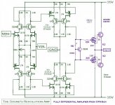
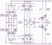
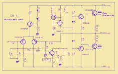
your last scheme suggested me that the stadium entrance
practically perfect
is already a VAS
therefore simply repeat symmetrically
to get the signal close to the ground
with a double gain (say sufficient)😉
WITHOUT CAPACITORS
and without reversal polarity risk (each rail to GND)
What do you think?
I hope you like this little revolution!
Regards
Hello
your last scheme suggested me that the stadium entrance
practically perfect
is already a VAS
therefore simply repeat symmetrically
to get the signal close to the ground
with a double gain (say sufficient)😉
WITHOUT CAPACITORS
and without reversal polarity risk (each rail to GND)
What do you think?
I hope you like this little revolution!
Regards
Attachments
Hi!Stee:
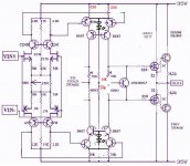
I even built this curcuit diagram,but not bridge, it sound very warm,purity, and have very good bass with elasticity and power.
But the second stage will hard to work balance, even though I use match transistor. Do you have any idea to let they work balance?
And I don't think the second use FET is best, FET have less gain in here, in my experience, will take bad sound than audion.
Hi QD!
to have more more stability
only one idea:
put floating point to ground
and adjust all from initial chain (bias and offset)
also in bridge mode you have more simmetry then past
(same load and local feedback on resistors in hot/cold)
so maybe can have better performance
do you think second FET must be more bigger
like the driver mosfets?
Attachments
Hi!Stee:
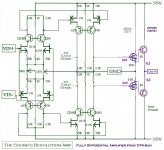
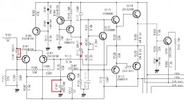
The second FET not need bigger, but use K170 and J74, I think the best current is less than 6MA, but the second C2240 and A970 must bigger, they can replace to B647 and D667.
But I prefer use this circuit, the A970/C2240 will have more stabilization.
In your last picture, it cann't adjust output stage,
Attachments
Hi!Stee:
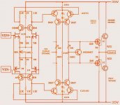
OK, but the 75ohms in second stage will too small, you can change to 220 ohms, If you hold to use 75 ohms, you can change the B647/D667 to bigger transistor and install radiator, like C5171/A1930.
If you build the circuit, you can try this circuit and match to your last circuit.
OK, but the 75ohms in second stage will too small, you can change to 220 ohms, If you hold to use 75 ohms, you can change the B647/D667 to bigger transistor and install radiator, like C5171/A1930.
If you build the circuit, you can try this circuit and match to your last circuit.
Attachments
Hi!Stee:
I benediction you can finish it and do well,
If it have some surge, you can add 10-33P hysteresis cap,
Input stage work on 1.5-2MA each is better.
I benediction you can finish it and do well,
If it have some surge, you can add 10-33P hysteresis cap,
Input stage work on 1.5-2MA each is better.

Hi QD!
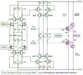
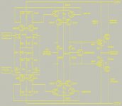
really my second job is cut capacitors:
http://www.esafono.it/nfcl.jpg
now I'm listening a Rotel multichannel
without capacitors (see drawing)
in bridge mode with balanced DAC (Lite DAC-AM)
with 4 times bias (5 to 20 mV on output power resistor)
and my AUDITORIUM balanced loudspeakers:
-->this is the maximum beautiful sound never listen<--
may be because complementary are not so similar
and certainly the philosophy of balancing is not a detail
so in this case Q111/B631 works passive like spring
better then other 4/5 fully complementary amplifiers that I have...
(...at the moment, because I'm building this Revolution Amp)
Attachments
Hi!Stee:
I am agree bypass the C101 and C107,will take sound clear.
I think, cancel C111, in technic is will bad, but in fact, it will change the sound,mabey you enjoy this sound.
I am agree bypass the C101 and C107,will take sound clear.
I think, cancel C111, in technic is will bad, but in fact, it will change the sound,mabey you enjoy this sound.
Hi
really is only 1uF
also to the other rail there is a passive complementary VAS
I'm beginning to think that this is the best solution
really is only 1uF
also to the other rail there is a passive complementary VAS
I'm beginning to think that this is the best solution
Hi Stee,
You can not recommend others do this. Those capacitors were installed for a reason. What you did was ill advised and recommending this to others is irresponsible. Especially without any warnings.
I'm not trying to rain on your parade. You should understand what exactly you are doing before changing those circuits. Certainly before sending others on that path.
-Chris
Did you check the DC offset after you were done??now I'm listening a Rotel multichannel without capacitors (see drawing)
You can not recommend others do this. Those capacitors were installed for a reason. What you did was ill advised and recommending this to others is irresponsible. Especially without any warnings.
Again, ill advised!! What you did only makes the amp run hotter and may cause some to go into thermal runaway. Higher bias = better sound is often an audio myth. All it does (at the very least) is overheat the parts and reduce operating life. Please don't tell me you leave the amp on all the time. That would be the only thing you could do to make things worse.with 4 times bias (5 to 20 mV on output power resistor)
I'm not trying to rain on your parade. You should understand what exactly you are doing before changing those circuits. Certainly before sending others on that path.
-Chris
hello Chris
sure
must be advise that need a DC check before connect loudspeakers
I have done that many time in different amplifier
and in output i always found less then 0.5V
normally around 0.35V and stable
that reported the sound to be decompressed
same for biasing
normally is set for minimum
for consumption
sizing and life of components... true
but class AB in my experience is never cool
exclusively for the sound (and also for non-linearity of the first stretch of curve)
or love class D !
I also noticed that the DC floating outgoing becomes longest
my last challenge traditions
as you saw in the project above 976
is to eliminate the automatic control of thermal drift
forcing a fixed bias and put an oversize radiator in each rail
and also build a pair of complementary amplifiers in bridge
but with only one active branch (again around perfect VAS)
course is experimental
I do not want to create a church
I'm trying to improve a sound that
normally has little realistic and natural
probably because people like so 😕 😉
😕 😉
sure
must be advise that need a DC check before connect loudspeakers
I have done that many time in different amplifier
and in output i always found less then 0.5V
normally around 0.35V and stable
that reported the sound to be decompressed
same for biasing
normally is set for minimum
for consumption
sizing and life of components... true
but class AB in my experience is never cool
exclusively for the sound (and also for non-linearity of the first stretch of curve)
or love class D !
I also noticed that the DC floating outgoing becomes longest
my last challenge traditions
as you saw in the project above 976
is to eliminate the automatic control of thermal drift
forcing a fixed bias and put an oversize radiator in each rail
and also build a pair of complementary amplifiers in bridge
but with only one active branch (again around perfect VAS)
course is experimental
I do not want to create a church
I'm trying to improve a sound that
normally has little realistic and natural
probably because people like so
😕 😉best circuit design of VAS
hello see last edition of 976
http://www.esafono.it/976.jpg
remember it's an idea only for EED - Experts Esoteric Designers
 😱 😱
😱 😱
also remember need a true balanced source (300$ Lite DAC)
hello see last edition of 976
http://www.esafono.it/976.jpg
remember it's an idea only for EED - Experts Esoteric Designers
😱 😱also remember need a true balanced source (300$ Lite DAC)
- Status
- Not open for further replies.
- Home
- Amplifiers
- Solid State
- Voltage Differential Amplification