I still do not understand. Driving a loudspeaker in high impedance is a source of lots of distortion, in fact the cone is undamped and free to oscillate at its own mechanic and cabient resonant frequencies. This is the reason why triodes has best sound than pentodes, and the idea for voltage NFB, to lower the output impedance seen by the moving coil to damp its own resonances, you are doing exactly backwards.
I do not understand too,
probably this is another place when the theory is not equal to the practice😕
but my best sounding ss amp was V to I converter with high output impedance.
It drove 16 Ohm full range speaker with the sound, quality and timbres not heard before,😉
I wonder that it was because of self-undamped-resonants...🙄
Yes, probably.
The theory/practice agree: voltage drive is the correct way to drive a speaker, except for those rare speakers designed for current drive. That assumes, of course, that the aim is hi-fi rather than boom and tizz.
The theory/practice agree: voltage drive is the correct way to drive a speaker, except for those rare speakers designed for current drive. That assumes, of course, that the aim is hi-fi rather than boom and tizz.
This simple circuit allows for control of the speaker cone.
It is also possible to access the "true motional driver" hidden behind the parasitic electrical components of a real speaker, by synthetizing an equal and opposite impedance (negative).
The difficulty is that the main parasitic component, the copper resistance, varies heavily (and dynamically) with the drive; this requires thermal image compensation.
An amplifier performing that task implicitly servoes the voice coil movement.
I have made some tentatives into that direction, and Stephane has advanced on the theoretical aspects and provided electrical <=> acoustical models in LTspice.
http://www.diyaudio.com/forums/solid-state/165867-servo-sound-made-belgium-2.html
Yes, probably.
The theory/practice agree: voltage drive is the correct way to drive a speaker, except for those rare speakers designed for current drive. That assumes, of course, that the aim is hi-fi rather than boom and tizz.
Obviously. Any inductance must be driven at low impedance (also motors, and transformers) and capacitive loads with current generators.
The guy above surely like resonant bass boost and as the case, a trombone, a contrabass, a electric bass and a tom all sound equal: the resonance of the mechanical-acoustical system in place the resonance of the musical instrument. Puaj... Not for me.
no
the guy bellow likes the music🙂
but will be not arguing about magic/knowledge😉
Obviously. Any inductance must be driven at low impedance (also motors, and transformers) and capacitive loads with current generators.
The guy above surely like resonant bass boost and as the case, a trombone, a contrabass, a electric bass and a tom all sound equal: the resonance of the mechanical-acoustical system in place the resonance of the musical instrument. Puaj... Not for me.
The equation B*l*I= d²s/dt²+ds/dt+....
indicates clearly that the enforced cone motion follows the current I and not the voltage applied.
Yes, probably.
The theory/practice agree: voltage drive is the correct way to drive a speaker, except for those rare speakers designed for current drive. That assumes, of course, that the aim is hi-fi rather than boom and tizz.
Voltage drive gives you a large amount of damping of the fundamental resonance, but it does not necessarily give you the smallest amount of (non-linear) distortion. In fact, you make the driving force sensitive to the non-linear self inductance of the voice coil and to compression effects due to voice coil resistance increase due to self heating, as pointed out in the AES papers referred to earlier in this thread. As frequency response errors are easier to equalise out than distortion, I think there is a case for current drive.
I agree with you, though, that the proposed circuit is just a complicated way of making a voltage amplifier.
Member
Joined 2009
Paid Member
Perhaps one method for some improvement is pre-distortion. Instead of trying to servo the cone motion in real time, measure the output of the speaker and use that to determine a level of pre-distortion that improves overall performance. Ideally, measure at the listening position as this will allow for some correction of room/boundary affects. Of course it isn't dynamic, it will necessarily be limited, but it will correct some of the deficiency in a system. One hopes it can be designed to 'do no harm' by worsening performance.
maybe a solution?
Hi
I tried to follow the links from you and found this site: Motional feed back amplifier - Electronic Circuits and Diagram-Electronics Projects and Design
Being the chemist I can see one current gnfb, one current gpfb (global positive feedback). Please alight me if I am wrong.
The positive feedback is taken in the way like current amps are working.
Is this a play to damp electrically speaker’s cone?
The overall distortion of the amp is rather high (attached asc file) but the author claims that the sound is extraordinary.
Another one with specific taste?🙄
Attachments
This appears to be precisely the mistake I mentioned in an earlier post: an assumption that as force is proportional to current so must motion be too.hahfran said:The equation B*l*I= d²s/dt²+ds/dt+....
indicates clearly that the enforced cone motion follows the current I and not the voltage applied.
The equation B*l*I= d²s/dt²+ds/dt+....
indicates clearly that the enforced cone motion follows the current I and not the voltage applied.
Try to drive a simple DC motor in current mode and test how much force can you get at the axis, and velocity. The motor will be very easily stopped indicating few torque. Same as speakers.
Member
Joined 2009
Paid Member
Bigun, this is what I say a post before, but try to do this in an ultrasonic frequency isn't too easy.
I see two main obstacles: while floating a motor for several milliseconds just the time to measure the back emf poses no particular problem, doing the same would be problematic in the case of a speaker.
Another problem is that motor speed and back emf are scalar variables, ie just a numerical value whereas the sound is more complex, vectorial or multidimensional depending on your interpretation.
Even if you try to read the instantaneous value at the time you extract the data, it will be polluted by what has happened before and the parasitic elements of the driver.
Devising a mathematical transformation capable of taking all that into account would be practically impossible.
That is the reason why I think that neutralization of parasitic parameters of the speaker is the way to go (the least worst anyway).
That way, you can arrive at a pure voltage drive, where the speed of the voice coil depends only on the idealized drive voltage, independent of forces applied to the cone (there are obviously practical limits).
The same is also done with DC motors for servo systems; it's called transducer configuration, or something similar, I don't remember the exact name, but in substance, that is exactly what is done: create a negative resistance opposite to that of the motor to transform it into its ideal model.
In the case of a motor, things are much simpler though.
For a speaker, you need to synthesize the conjugate electrical impedance (excluding motional parameters), and adapt it dynamically to the thermal variations induced by the signal, not an easy task.
Thank you for the feedback to you all 🙂
It is true, unfortunately, in the simulations of a woofer voice coil, low frequency oscillations are shown.
But I'm not giving up so easily. The next attempt is already in work....
My experience is that after a certain high quality of an amplifier no longer perceptible differences. But you can hear some differences between regulated and unregulated speakers.
My ambitions of my tinkering is to implementing such an also audible improvement.
When I have worked(simulated) out a decent circuit, I will build two circuits. One TDA7293 with a 'sensor' and the other as usual VFB amp.
As I said in an earlier post: people who understand servo systems eventually give up, realising that they can't solve the problems. Others may carry on even longer, not realising what the problems are.
Thank you for the feedback to you all 🙂
It is true, unfortunately, in the simulations of a woofer voice coil, low frequency oscillations are shown.
But I'm not giving up so easily. The next attempt is already in work....
My experience is that after a certain high quality of an amplifier no longer perceptible differences. But you can hear some differences between regulated and unregulated speakers.
My ambitions of my tinkering is to implementing such an also audible improvement.
When I have worked(simulated) out a decent circuit, I will build two circuits. One TDA7293 with a 'sensor' and the other as usual VFB amp.
The AES concept is simpler and effective. Just current drive the speaker and
compensate its mechanical to electrical characteristics to any degree ( as long as the physical limitations of the speaker allow that) with a negative
real and a conjugate complex output impedance of the amp.
There are a bunch of other methods to achieve this but AES has the advantage of getting along with simple engineer's math. It works great.
The reason why servo systems are far more limited than the AES method is easy to be seen from the electrical-mechanical motion differential equation
One can EITHER compensate acceleration or velocity or location while AES compensates
all three.
One can EITHER compensate acceleration or velocity or location while AES compensates
all three.
I had success, the amp is working stable now. 🙂
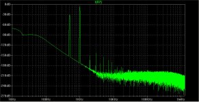
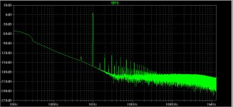
So I did several tests. An amp is loaded with a voltage source. The voltage source has a resistance of 10 ohms, a frequency of 500 Hz and an amplitude of 0.5V (resonance of a speaker at 500Hz).
Once the amp is driving as pure CFB(1),
as VFB(2)
and finally my idea, CFB-sensor(3)
As presenting the results is not worth a build. 😛
Attachments

- Status
- Not open for further replies.
- Home
- Amplifiers
- Solid State
- Voice Coil as sensor for control.