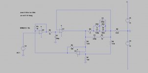
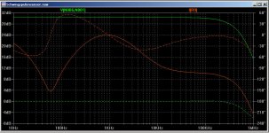
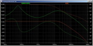
This simple circuit allows for control of the speaker cone. The power amplifier operates as a current amplifier. Without regulation caused the current amp a strong peak in the resonant frequency of the chassis. To avoid this, the voltage is measured at the voice coil and is compared with the input voltage. An opamp before the current amp corrects the frequency response. This applies not only to the resonant frequency but also for the whole band. As simple as it works you can't control the mid neither never mind the treble with an other technology.
The simulation works well so far.
The simulation works well so far.
Attachments
This simple circuit allows for control of the speaker cone. The power amplifier operates as a current amplifier...
Hi Moshfet
some good staff here too Current-Drive - The Natural Way of Loudspeaker Operation
If you are measuring the voltage and using that to adjust the current drive, then what you have is voltage drive (created by heavy negative feedback). Good - for that is the way most speakers are intended to be driven. Just don't pretend this is 'current drive' - is isn't.
Hi padamiecki
Hi DF96,
that is the question. If my assumption is correct, then you can hear (measure) a difference between my controlled version and a uncontrolled (a normal voltage driven amp) active Speaker.
Right, i got it 🙂Hi Moshfet
some good staff here too Current-Drive - The Natural Way of Loudspeaker Operation
Hi DF96,
that is the question. If my assumption is correct, then you can hear (measure) a difference between my controlled version and a uncontrolled (a normal voltage driven amp) active Speaker.
Any difference is merely because one or other method is a poorer approximation to a true voltage drive. You can check this by inserting an impedance in series with a voltage source.
Basically, all your circuit does is remove the local feedback inherent in most output stages and entirely replace it with global feedback. Most people would regard this as a backward step, and strive to do the opposite.
True current drive is only possible with a loudspeaker which has been specially designed for this. That means heavy mechanical damping of the bass resonance, and either a full-range unit or series-connected crossover instead of the usual parallel-fed crossover.
All other attempts at current drive will either result in a huge bass resonance and very lumpy frequency response, or (like yours) are not really current drive at all but just disguised voltage drive.
That means heavy mechanical damping of the bass resonance, and either a full-range unit, digitally crossed multiway unit, or series-connected crossover instead of the usual parallel-fed crossover.
fixed 😉
Inside the cabinet and in the speaker's mechanic, there exists phase rotations, that will convert negative feedback into a positive one causing entire system to oscillate. How will you control them?
I can't see what local Feedback do you mean 😕Basically, all your circuit does is remove the local feedback inherent in most output stages and entirely replace it with global feedback. Most people would regard this as a backward step, and strive to do the opposite.
True current drive is only possible with a loudspeaker which has been specially designed for this.
No. It is possible to drive a normal bass woofer in current drive when you control the speaker with a sensor.
If you're fussy, you could see this as a negative voltage feedback. Others speak of regulated speakers...
I'm afraid my English is not good enough to illustrate my idea.😱
Hi Osvaldo,
this amp is only for active speakers, so I don't see the danger of oscillations.
A test with a TDA7293 is quick to set up 🙂
this amp is only for active speakers, so I don't see the danger of oscillations.
A test with a TDA7293 is quick to set up 🙂
I accept your amendment.qusp said:fixed
Most amplifier (and opamp) output stages are some version of an emitter follower circuit. This has inherently high local negative feedback and so low output impedance. It approximates a voltage source. A much better approximation is obtained by adding global negative feedback too.moschfet said:I can't see what local Feedback do you mean
Perhaps I should have said 'only sensible' instead of 'only possible'. Seeing sensing as feedback is not being fussy, merely being correct. A normal amplifier senses the voltage at the loudspeaker, as this (apart from a few cables etc.) is where the NFB is taken from. Essentially all you are doing is replacing the output stage with a different type, perhaps less suited to the task. It is generally best if global NFB augments what the circuit would naturally do anyway, not fight against what the circuit wants to do.No. It is possible to drive a normal bass woofer in current drive when you control the speaker with a sensor.
If you're fussy, you could see this as a negative voltage feedback. Others speak of regulated speakers...
This idea crops up from time to time, either because people don't realise that it doesn't work too well and is not new anyway, or because they think they have an amazing new idea (usually with complicated mathematical analysis) to get round the problems. People who are experts in servo design usually give up eventually. Others may struggle on because they don't realise what they are getting into.
Once again, how does your circuit discriminates voltages flowing into the coil and the voltages induced by standing waves in the cabinet acting in the speaker as a microphone.
@DF96
@Osvaldo
I'm not sure, so I will test it.
Yes, thats right but I spoke from voltage feedback and that was your objection.Seeing sensing as feedback is not being fussy, merely being correct.
I agree.It is generally best if global NFB augments what the circuit would naturally do anyway, not fight against what the circuit wants to do.
@Osvaldo
I'm not sure, so I will test it.
A bit of theory.
What I'm trying to mean is as follows:
The mechanic vibrating system of a speaker is a DC motor: a coil, a magnet,
and mechanic output. So, this system can act like is usually called 4 quadrant motor. Assuming an arbitrary polarity of the moving coil, when you put a
small DC voltage across it, it will respond with a DC current flowing trough
the wire, generating a magnetic field, and it interacts with the fixed field
generated by the magnet, and then causing cone (or the axis of a motor) to
move from its initial position. If you revert the polarity of such DC voltage, happens the same but moving the coil and cone (or the axis) in opposite direction. This are first and third quadrant.
When the coil becomes undriven, the system goes to the standstill position,
and then the coil moves trough the magnetic field generating a DC voltage
across the coil winding which it usually flows through the low output amplifier's impedance, and generating a current which in turns brakes the cone. These are second and fourth quadrants of the operation.
So, suppose you have your speaker in a box. You apply a voltage pulse to the
coil. The cone will move, i.e. forward. Then you will ear a "pop" sound
caused by the air moved by the cone. When you remove the excitation, the cone will return to its balance or equilibrium position causing a "boom" sound
meaning and undamped oscillating cone at the natural mechanical frequency of the resonance of the moving parts.
The air moved in the box, also will refract in the walls of the box, and some
time later will impact in the cone causing a new cone movement and voltage
appearing in the moving coil ends.
How the hell your system will recognize which of the above mentioned voltages in the coil are the desired and undesired ones?
In PWM controls, DC voltages are measured when the off state of the power stage, and then sampled and hold in a special circuits, and then, a tachometric voltage is obtained in this way. You can't do it without generating severe audio distortion.
In case you can't distinguish this difference, and at some certain time offset
in the received acoustic wave converted into electric current again, your
system may attempt to compensate for an out of phase signal, which also is out of phase mechanical or acoustically, and then positive or regenerative
feedback is present, and your system undoubtedly will oscillate.
Cordially, Osvaldo.
Thank you for your detailed execution. There are some points I have also read in the book 'current-driving of loudspeakers'. That will not mean, that I have understood all of it. But it was an interesting starting point for own thoughts.
My consideration was to feedback the voltage over the voice coil with U3 to U1. U1 compares the two signals and corrected them.How the hell your system will recognize which of the above mentioned voltages in the coil are the desired and undesired ones?
I still do not understand. Driving a loudspeaker in high impedance is a source of lots of distortion, in fact the cone is undamped and free to oscillate at its own mechanic and cabient resonant frequencies. This is the reason why triodes has best sound than pentodes, and the idea for voltage NFB, to lower the output impedance seen by the moving coil to damp its own resonances, you are doing exactly backwards. 
I suspect part of the confusion arises because people know that the driving force on the voice coil is proportional to instantaneous current. They therefore wrongly assume that the sound output must also be proportional to instantaneous current. They forget that they have a suspended lump of stuff with restoring 'springs' (so a driven damped harmonic oscillator) which is also a finite size insufficiently-stiff piston displacing air. It all gets messy, and history shows us that the best option is actually voltage drive over a restricted bandwidth.
yep, it seems the best way for now, at least from my POV is to use best practices and multiamp (voltage driven), use digital correction/convolution to start the feedback loop again after the speaker drivers, on the other side of the room at the mic. still leaves the motor to have error, but its driven with the opposite of that error + the room error.
yep, it seems the best way for now, at least from my POV is to use best practices and multiamp (voltage driven), use digital correction/convolution to start the feedback loop again after the speaker drivers, on the other side of the room at the mic. still leaves the motor to have error, but its driven with the opposite of that error + the room error.
...plus reverberations and resonances of room. The error will be high, and Mr Larsen will do its job.
+ the room error plus the room error?
I already mentioned the room error in the post you quoted...
its hardly new ground, the convolution system works quite well and error at the end isnt that high at all, much lower than passive XO, but there is only a limited sweet spot.
or maybe I have misunderstood you and you are not arguing my point, rather agreeing with it? Mr Larsen is well known but not sure still at the forefront
Last edited:
- Status
- Not open for further replies.
- Home
- Amplifiers
- Solid State
- Voice Coil as sensor for control.