Can VirtuixCAD show directivity without driver measurements? Means just by simulation.
Diffraction tool is able to simulate ideal flat circular and rectangular radiators in closed or open baffle. Responses can be exported in horizontal and vertical planes. Long bevels are not supported.
Calculator tool is able to calculate off-axis response of ideal flat circular or rectangular radiator to single direction in horizontal or vertical plane.
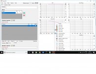
If I open a new project and try to see the directivity, nothing happens, pls see attachment.
I am able to see directivity in the sample project Epe-3W_demo and I noticed several files in Epe-3W_demo\Far directory, are these files generated by tool (simulated VituixCAD output 🙂 ) or should the user supply them by some other means (not simulated, VituixCAD input 🙁 )?
I am able to see directivity in the sample project Epe-3W_demo and I noticed several files in Epe-3W_demo\Far directory, are these files generated by tool (simulated VituixCAD output 🙂 ) or should the user supply them by some other means (not simulated, VituixCAD input 🙁 )?
Attachments
If you just want to play around as a simulation without measurement files then you will at least need a frequency response of the driver from a datasheet.
Use the SPL Trace functionality from the tools menu create a frequency response file by capturing an image from the driver datasheet.
To obtain the directivity response use the Diffraction feature from the tools menu, create a box of your design along with the speaker driver diameter, open the half space response (your SPL trace), tick the Full Space option then feed the output to your selected driver.
Last edited:
Fully simulated responses can be generated with Enclosure and Diffraction tools. See this video: Creating off-axis responses with VituixCAD Diffraction tool
Note that recording is done with old VituixCAD 1.1 with formal ladder crossover network. Version 2 has free form network so component positioning and wiring should be done by user.
Disclaimer: Generated directivity is inaccurate and not recommended for final speaker design. Recommended design procedure is listed in user manual.
Last edited:
Hello,
Would it be possible in increase the number of "Scenarios"?
I find it would be handy to have more than 5, perhaps 10?
Thank you,
David.
Would it be possible in increase the number of "Scenarios"?
I find it would be handy to have more than 5, perhaps 10?
Thank you,
David.
"Scenarios"
I've been thinking half a year that "scenario" is probably too fancy and philosophical term for that feature. Maybe "Stage" would be better? Few other synonyms such as "phase" or "version" are possible, but those are kinda reserved words for something else.
Thanks guys! Hopefully I can keep this software alive and add some new features in the future, though new ideas and motivation are slowly decreasing. Maybe because it's already so perfect 😀
-Kimmo
Unless you are getting paid for your software it can be hard to keep it improving.
I have been writing PCBCAD software since around 1990 after being disillusioned with a copy of EasyPC pcb cad software.
Its just grown and grown.
Sadly these days too many competitors so sales and price tend to suffer a bit.
One addition I would definitely add to Vituix under the "Help" menu is "Donate",
"If you find this software useful and wish to donate to its continued development, Click Here"
Where people can click and send $20, $50 or $100 via Paypal or whatever...
(BTW I sent €50.00 last year)
Keep up the good work Kimmo!
Thank you,
David.
I would definitely add to Vituix under the "Help" menu is "Donate"
So far I've trusted that generous people have found PayPal links from home page and changelog, but now it's is also in Help menu. Thanks for all donors!
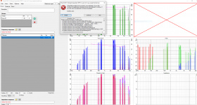
Exception
Got this exception just now. Am attaching a screenshot. There does not seem to be any way to enlarge the window to get a fuller set of lines, or is there any way to save these messages, so this is the best I could do.
I clicked "Continue" after this, so the application continued working. I saved the file and exited. Then I re-started the application and re-loaded the file, and I immediately got the same exception again. It probably means that the exception is being re-triggered by the data in the file.
I had loaded FRD and ZMA data of 3 drivers and defined a crossover, and was tweaking the crossover when this happened. To be precise, I was trying to add a parallel notch block to the crossover when this exception happened. At the same instant, all the graphs got messed up too, and the Y axis scales of all the graphs changed to infinitesimal values, like -150dB and so on.
I'm running the latest version of VituixCAD, because it keeps auto-updating itself. I'm running on Win10 with 8GB RAM, and as Kimmosto probably knows, I'm a happy user and have completed a few projects with it.
Should I just start all over again, add the same drivers and crossover and resume? Is there anything else I may do to help?
Attachments
Last edited:
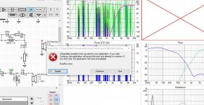
This is too close a correlation to be accidental, isn't it? Maybe Kimmosto can look at parallel notch entries in the library.Yes, this happened here also when adding a parallel notch from the library.
I am sure he already is ...
edit: This is happening even if a PN from the library is pulled to an empty project. So I guess not measurement data related.
edit: This is happening even if a PN from the library is pulled to an empty project. So I guess not measurement data related.
Last edited:
This error is very familiar. Exception was ignored with earlier versions and the same workaround is obviously needed also for the new code with svg export. But this will not happen today because I'm 434 km from home without PC.
Cool! Hope it was a vacation. 🙂I'm 434 km from home without PC.
- Home
- Design & Build
- Software Tools
- VituixCAD