That Measurement Preparation document says "...asymmetrical
constructions should be measured both negative (to left) and positive (to right) off-axis angles...". I was rather confused about the meaning of "left" and "right", because the text does not give the context of "where the eye is". Is the eye behind the speaker, looking towards the microphone? Or the other way round? "Left" and "right" give opposite angular directions from these two views.
From looking at the polar plots in Vituix my guess about positive/negative horizontal angles was as you wrote ("inside"=positive angle, "outside"=negative angle). However, it seemed the diffraction calculator results were consistent with my measurements only if the angle direction was the other way round.
Also, the X/Y/Z coordinate system is rather awkward... it's left handed!?
Can someone confirm that "inside"=positive angle and "outside"=negative angle is correct?
Also, does the baffle diffraction calculator use the same convention, or is it inverted?
Edit: crossed post with kimmosto.
Also, does the baffle diffraction calculator use the same convention, or is it inverted?
Logic is the same with Diffraction. Reason is that you could merge diffraction simulation to measured responses or use measured data for mid while simulated data for woofer.
I will add few images to measurement preparation document
New images available on page 4
An externally hosted image should be here but it was not working when we last tested it.
New images available on page 4
An externally hosted image should be here but it was not working when we last tested it.
Great! Now you just need to say that this is top view (not bottom view) for the horizontal angles. This might be intuitively clear for most readers, but not for all (me included).
This might be intuitively clear for most readers, but not for all (me included).
Now you can write yellow note that it's top view 🙂 Anyway, asking of this kind of details is not so rare. Next questions could be for example:
a) Is rotation center on baffle surface if driver is rear mounted?
b) Is rotation center on baffle surface if driver is not flush mounted?
c) What is rotation center with separate horn installed on the top of woofer box?
d) What is driver's Z mm coordinate with horn?
e) Can I measure both mid and tweeter at elevation of tweeter? This is what some gurus have recommended on discussion forum.
f) Can I measure both mid and tweeter at the same elevation; average of mid and tweeter? f1) Tweeter is dome f2) Tweeter is rectangular AMT.
g) What Z mm coordinate should be for tweeter and woofer if stepped baffle is tilted 4 degrees back? Step from tweeter baffle to woofer baffle is 19 mm (woofer closer to listener).
...
Last edited:
Logic is the same with Diffraction.
Are you SURE?
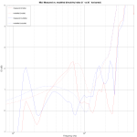
I used the Vituix diffraction calculator to determine the directivity index (DI) from the difference between on-axis and off-axis diffraction curves. My measurements show better consistency with the modelled curves if I invert the direction of the horizontal off-axis angles used with the diffraction calculator. This is how I did the attached figure.
Could this be a bug in Vituix? Is there a simple way to test?
Attachments
Are you SURE?
No. My previous answer was simply wrong. Sorry about that.
Axial line from mic to baffle surface is straight (just a point from mic's view), and speaker rotates around end point of that axis; positive angles to counter-clockwise from top view.
I need to check few things and reverse logic if needed.
Logic is the same with Diffraction. Reason is that you could merge diffraction simulation to measured responses or use measured data for mid while simulated data for woofer.
So this answer was B.S. Angles in measurement data are mirrored compared to responses exported with Diffraction tool. Rotation angles in horizontal plane are specified generally: "positive to counter-clockwise from top view" for baffle rotation in Diffraction tool, driver rotation in main program and mic rotation in measurement data.
At the moment diffraction simulation can be merged with measurements as far field responses if baffle is symmetrical (enough). That is typical situation with woofers in horizontal plane, but in other cases not so much.
Easier cheap trick would be changing of angle sign in Diffraction tool, just exports or whole tool. That is probably what I will do because angle values are located in "Axis" group which hints that mic/ear rotates. Not the baffle, how it is now and documented also in user manual.
Last edited:
Rev. 2.0.10.2 (2019-01-04)
Diffraction tool
* Sign of rotation angle changed while directivity export for compatiblity with measurement data.
* Tooltip of Angle Hor and Angle Ver text boxes changed to "Baffle rotation ..."
Diffraction tool
* Sign of rotation angle changed while directivity export for compatiblity with measurement data.
* Tooltip of Angle Hor and Angle Ver text boxes changed to "Baffle rotation ..."
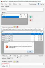
well at least I don't get that error message but I also don't see my measurement data showing up in the graphs...
Thanks.
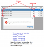
renamed as suggested and it works. had to take the "58" out of the name also
Renaming was not needed. Original ARTA style filenames with "hor" or "ver" keyword before angle value were perfectly legal. Just change Search direction to From end in Angle parsing from filename group in Options window. That is default/initial value which works with both ARTA and CLIO.
Can Vituix export the biquad coefficients corresponding to the transfer function of a passive filter
Not directly. Primary method to emulate passive crossover with dsp device (miniSHARC, 2x4HD etc) or application (EquAPO or compatible) is to export impulse responses of drivers' transfer function, and use them with FIR convolver.
Secondary method is to create active crossover with generic active blocks and optimize each active way so that target response is 'Filter gain of driver' exported from passive version.
I don't emulate passive with active if speaker is standard boxed 2...4 way, because that would not change much. Parameters / component values are simulated anyway, and possible tuning is needed to one..two components. Of course if there is big risk that whole design sucks, active test platform is easier and cheaper to reuse.
Last edited:
...export impulse responses of drivers' transfer function...
I meant electrical transfer function at driver's terminals which is "Driver in D.." in Signal to export combo box at Impulse response window.
Rev. 2.0.10.3 (2019-01-07)
Main program
* Component values can be entered with metric prefix (p,n,u,m,k,M,G,T) to Parameters grid and Tune block window.
* Component values are shown with automatic metric prefix in crossover schematic, except unitless values (Q,R), frequency in Hz and gain in dB.
* LCR component values are shown with automatic metric prefix in Parts list window.
Hi kimmosto,
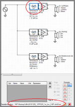
Over think the latest 4-6 software versions learned about and begun use practical "Transfer funchtion file" block to research and simulate stuff and ideas, thanks for that feature of possibilityes. Always had one minor bug with that feature and manual doesn't hint i'm doing something wrong about file and format, culprit is even session is 100% sure saved and path for transfer file is looking right at lower left corner then after a new re open of session then various plots doesn't reflect correction from transfer file, path at lower left corner is looking right and i have to reguide it down there vis explore dialogs to same file as path told for each of used Transfer funchtion file blocks to get various plots update to intended situation, visual example is below.
Over think the latest 4-6 software versions learned about and begun use practical "Transfer funchtion file" block to research and simulate stuff and ideas, thanks for that feature of possibilityes. Always had one minor bug with that feature and manual doesn't hint i'm doing something wrong about file and format, culprit is even session is 100% sure saved and path for transfer file is looking right at lower left corner then after a new re open of session then various plots doesn't reflect correction from transfer file, path at lower left corner is looking right and i have to reguide it down there vis explore dialogs to same file as path told for each of used Transfer funchtion file blocks to get various plots update to intended situation, visual example is below.
Attachments
- Home
- Design & Build
- Software Tools
- VituixCAD