In my opinion, the fundamental problem is the value of the measurement signal.
Do you mean voltage level or series resistance i.e. current?
The very pleasant procedure is used by SB accoustic. The datasheet is on the page.
That document and Beranek/Mellow was my original reference for calculations with added mass method. But as I mentioned, calculation is not anymore ideal Mms=Mx/((fs/fm)^2-1). It's weighted towards Mms=Mx/(fs*Qem/fm/Qes-1) which is used for example in LIMP(ARTA), MLSSA SPO and maybe REW too.
Same story with closed box method. VCAD calculates Vas as weighted average of Vb*(fc*Qec/fs/Qes-1) and Vb*((fc/fs)^2-1). The first one is acknowledged as better, but difference to added mass method could stretch quite high.
I don't have "The Truth" so we have to accept some error and uncertainty.
Last edited:
Kimmo, do not get a simple tutorial on MIB? I think those who want more accuracy would like to try this method, although more complicated.Rev 2.0.9.4
Mic-in-Box -function added to Calculator tool is kinda experimental. It's just 2nd order high-pass which compensates "room gain" if sub/woofer is measured so that mic is located inside the box. Generally, this method should be slightly better for closed boxes than traditional near field (outside the box), but frequency range could be more limited.
This feature could also be in Merger tool, but I suppose it won't be so popular as NF measurement due to more difficult mic arrangement.
Your opinion on the Cepstral Deconvolution method that John Kreskovsky has integrated into his program? It's a bit more complicated to set up, but the microphone stays at the reference point.
do not get a simple tutorial on MIB?
This is also linked to user manual: Measuring Loudspeaker Low-Frequency Response
but the microphone stays at the reference point.
That won't necessarily help much due to need of directivity data (-180)..0..+180 deg, but I haven't investigated all possibilities. Existing features and methods have been adequate at least for box speakers, horns and OBs. Complex cardioid systems need something else.
I mean voltage or current level, depends on the method used, the value of the resistor also seems to have an effect. For example, in the mentioned SB acoustic they use a 150 ohm resistor and 1 V at the FS. Hence, this is neither a constant voltage nor a constant current measurement (the value of the resistor is not nearly large enough to approximate constant current, which is not the intention either). This sentence also confirms that standards are set, but I dont know or even fixed.Do you mean voltage level or series resistance i.e. current?
That document and Beranek/Mellow was my original reference for calculations with added mass method. But as I mentioned, calculation is not anymore ideal Mms=Mx/((fs/fm)^2-1). It's weighted towards Mms=Mx/(fs*Qem/fm/Qes-1) which is used for example in LIMP(ARTA), MLSSA SPO and maybe REW too.
Same story with closed box method. VCAD calculates Vas as weighted average of Vb*(fc*Qec/fs/Qes-1) and Vb*((fc/fs)^2-1). The first one is acknowledged as better, but difference to added mass method could stretch quite high.
I don't have "The Truth" so we have to accept some error and uncertainty.
The voltage that should be applied to the terminals of the drive unit
depends on its size/type.
This is also linked to user manual: Measuring Loudspeaker Low-Frequency Response
That won't necessarily help much due to need of directivity data (-180)..0..+180 deg, but I haven't investigated all possibilities. Existing features and methods have been adequate at least for box speakers, horns and OBs. Complex cardioid systems need something else.
Yes, of course I agree.
I thought this method does not need near-field measurements, of course, directional characteristics are expected. It simply removes reflections in the room without the need difractive pattern and a merge of near and far field.
EasyLab manual, chapter 16.2, page 16/41, Cepstral Deconvolution
I've had SoundEasy up to version 12 so never tested this feature.
In addition, before you start using this tool, please be aware, that close-mike measurement technique, coupled with diffraction analysis, will yield equally good, if not better results, simply because the reflections are attenuated by the virtue of the measurement technique. However, the close-mike technique is also complex, and requires utmost attention at every stage of summations and diffraction modelling. Therefore, once you become confident with Cepstral Deconvolution, you may try to use it for all quick, first-cut activities, and move to close-mike measurements for the final results.
I've had SoundEasy up to version 12 so never tested this feature.
Last edited:
I have a question on how to minimize the errors of optimizer, as shown by the differences betwem simulation and measurements.
Can we run optimizer only for the frequency area indicated by the pink line, but without changing the other frequencies?
It is like creating a custom target keeping the good areas and creatinga target only for smaller speccific areas that need further optimzation.
Can we run optimizer only for the frequency area indicated by the pink line, but without changing the other frequencies?
It is like creating a custom target keeping the good areas and creatinga target only for smaller speccific areas that need further optimzation.
Can we run optimizer only for the frequency area indicated by the pink line, but without changing the other frequencies?
Yes. Squared error while optimizing is calculated within range of magenta target line. Not below and above. See user manual page 19:
So you can optimize quite narrow band, but you should not optimize components which do not affect directly to target range.Target lines are set in SPL and Power & DI charts. Optimizer calculates squared error within frequency range of each target line.
Yes. Squared error while optimizing is calculated within range of magenta target line. Not below and above. See user manual page 19:
So you can optimize quite narrow band, but you should not optimize components which do not affect directly to target range.
Thank you for your prompt reply, but because some components affect both the magenta and the other areas beyond that, the optimizer improves the one area but affects also the other areas.
Can we keep the other areas totally unchanged and achieve only what improvements are possible within the magenta area?
Actually it will be like creating a new customized target instead of the straigt line.
Another way might be working, if we could modify the shape of the target, using additional tilt or EQ filters to modify the magenta curve from straight line.
Last edited:
Can we keep the other areas totally unchanged and achieve only what improvements are possible within the magenta area?
Not at the moment, but selection of optimized parameters is quite good method to control how frequencies outside the target area react. Close to nothing will happen if you don't select components which affect there, though sometimes that is not possible.
One option is to add checkbox which sets current response as a target outside straight target area once you click Optimize button.
^^Could you send few examples to my e-mail? This limit has not been problem with my projects so I'm a bit interested what kind of cases need curved target or locking of bands outside straight target.
The latest setup package includes sort of experimental library blocks for passive 2-way and 3-way speakers. Main filter components are designed with f, Q, Z and A parameters via Tune block window. Few spare components are initially open or shorted.
This might help with common filter topologies if manual tuning or optimizing of individual components is personally not so interesting.
This might help with common filter topologies if manual tuning or optimizing of individual components is personally not so interesting.
An externally hosted image should be here but it was not working when we last tested it.
An externally hosted image should be here but it was not working when we last tested it.
I am a noob trying to get into VituixCAD. Is there a "tutorial for dummies" to help newbies understand the concepts / building blocks of VituixCAD, and how these work together? I know there is a manual, but this seems to "just" explain the individual commands and features. I am a bit lost in this jungle because I am missing the big picture...
This video shows basic drawing features: YouTube
Block insertion is also explained but quite briefly. Tuning via context menu (right click on the block) -> Tune block...
No video for block creation. Parametrized blocks are not very simple to make. I can make new library blocks to setup package if they are helpful for many users.
More information for assigning driver instances to measurement data in Drivers tab can be found in this thread, around post #780.
Ok, thanks for this video on how to draw filter circuits.
However, I am looking for something else. VituixCAD seems to consist of different toolboxes for different things (box/enclosure tuning, baffle/dispersion modeling, filter designs, and maybe more that I missed so far). How do these toolboxes work together? How do they link together?
I don't understand the big picture of how a VituixCAD project works as a whole.
^Section "Checklist for designing a loudspeaker" in user manual on pages 4-5 tries to be recommended workflow at least for common loudspeaker types such as single or multi-way in closed or ported enclosure. Something about measurements is explained in Measurement preparation document only. More about Merger on youtube video. The latest manual for 2.0.9.5 (2018-12-31) includes also Convert IR to FT tool in the checklist.
Final design order and methods depend on speaker type and measurement facilities: is near field measurements needed, far field measurements possible or mandatory for all radiators, what responses needs to be simulated etc. Therefore results of 'tools' are transferred as txt/frd files to next stage. For example from Convert IR->FR to Merger, and finally to crossover design in the main program. Separating of raw measurement data, processed measurement and simulated response data from crossover designer helps also creating variations and cloning.
Final design order and methods depend on speaker type and measurement facilities: is near field measurements needed, far field measurements possible or mandatory for all radiators, what responses needs to be simulated etc. Therefore results of 'tools' are transferred as txt/frd files to next stage. For example from Convert IR->FR to Merger, and finally to crossover design in the main program. Separating of raw measurement data, processed measurement and simulated response data from crossover designer helps also creating variations and cloning.
Rev. 2.0.10.0 (2019-01-02):
* Shortcut Ctrl+P added for Optimizer, F9 for Convert IR to FR.
* Ideal Transformer added to component menu. Floating connection (without ground symbol or wire from secondary to node 0 ) enabled with hidden 1 MOhm resistor from bottom right terminal to node 0.
* Shortcut Ctrl+P added for Optimizer, F9 for Convert IR to FR.
* Ideal Transformer added to component menu. Floating connection (without ground symbol or wire from secondary to node 0 ) enabled with hidden 1 MOhm resistor from bottom right terminal to node 0.
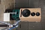
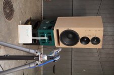
I am slowly getting into Vituix. Something I couldn't figure out until now is the direction (sign) of the horizontal (and vertical) angles. Please take a look at the attached photos ("inside" and "outside"). Which one would correspond to a positive horizontal angle in Vituix?
I need to get this right because the mid+tweeter are not centered on the baffle, and I'd like to use baffle diffraction calculator in Vituix to take a look at the asymmetric dispersion.
I need to get this right because the mid+tweeter are not centered on the baffle, and I'd like to use baffle diffraction calculator in Vituix to take a look at the asymmetric dispersion.
Attachments
Left side is the minus side and accordance to your outside so right side is the plus side and accordance to your inside.
Below kimmosto link is a good read.
Below kimmosto link is a good read.
...Something about measurements is explained in Measurement preparation document only...
Last edited:
Which one would correspond to a positive horizontal angle in Vituix?
Outside.jpg has negative measurement/mic angle, and inside.jpg has positive.
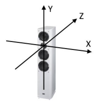
From listener's view:
- mic/ear move right => more positive horizontal angle
- mic/ear move up => more positive vertical angle.
In other words, measurement angle changes towards more positive values when turntable is rotated clockwise (from top view) while mic position is constant.
I will add few images to measurement preparation document because short description in user manual for driver rotation does not explain this.
- Home
- Design & Build
- Software Tools
- VituixCAD