Same for you. Follow measurement instructions and you will never see extrapolated data and problems it may cause.
I don't follow, I am talking about measurements that have been done in the past. So older datasets.
I also don't follow what you mean with "measurements instructions"
Measurements are done with ARTA as usual.
Although these days the only change I am making is doing the time window in VituixCAD. Which still gives extrapolated and false data below the time window frequency.
Right, I thought that was part of the calibration response.
Is there a similar setting for .frd files?
Is there a similar setting for .frd files?
Member
Joined 2003
Those settings are for the frequency response output, only the calibration file and “min phase” checkbox underneath are relating to the mic calibration.
Following the instructions for data generation, you would fill in the low frequency data with a near field measurement, so the extrapolated data in the windowed far field measurement becomes irrelevant.
Following the instructions for data generation, you would fill in the low frequency data with a near field measurement, so the extrapolated data in the windowed far field measurement becomes irrelevant.
I use professional Noise&Vibration software (Prosig DATS) and I usually process with high frequency resolution. so I normally have to decimate the files so that PCD can import them in the frd format (I just run a macro in Excell deleting some lines). How big a file can VCAD import in the frd format?
Member
Joined 2003
I ran a measurement at 192kHz, MLS sequence length 262144. Loaded IR-FR in VituixCAD, pressed near button and exported "full resolution. It created a file with 54327 lines, so at least that big.
A bit of diminishing returns for a screen display of frequency response data from 5-40kHz, any more than a few thousand data points is probably over-doing it.
A bit of diminishing returns for a screen display of frequency response data from 5-40kHz, any more than a few thousand data points is probably over-doing it.
frd file can contain almost infinite number of records but high resolution files are not recommended for normal XO design projects due to performance. Whole file is read and interpolated to internal frequency range and points when project is loaded or user changes frd scaling parameter; Scale, Delay, Invert, Mute, Smoothing, Minimum phase. Large files can be easily converted to small and fast ppo files with Scale (=1) function of Calculator tool.
Any chance of VituixCad having the option of setting the radiuses on individual box edges
Individual radiuses should be mathematically easy, but I'm not sure about UI. Internal data contains group of corners - not group of edges so clicking corner should highlight edge beginning from that corner.
Diffraction calculation is done in frequency domain. It uses simple LP filtering with exponent function for rounded edges - just like Bagby's sheets. Chamfers/bevels need calculation in time domain with generated impulse responses because multiple diffraction with different delays is more obvious.
It's doable but not probable that I would make that big change because it's a mistake to allow diffraction at HF. The best decision is to eliminate HF diffraction with long radius or combination of chamfer and long radius in edges close to HF radiator. We can control response errors to some directions with edge design but that is kinda fake which does not fix whole design.
The best decision is to eliminate HF diffraction with long radius or combination of chamfer and long radius in edges close to HF radiator. We can control response errors to some directions with edge design but that is kinda fake which does not fix whole design.
This was a problem where I was trying to use the Peerless NE64W-04 full range and cross it over with a Visaton W 130 X - 2 x 4 "sub" at 500 Hz.
How do you model the baffle step of the full range with round overs only at the side and the Full Range at the top edge of the box with no roundover?
I ended up putting a roundover at the top even though I didn't want to, just so it would model the baffle step in the diffraction section correctly.
David.
Or choosing Chamfers or Radiuses?
Forum member Fluid has presented simulations which show there is very little difference between a radius and a chamfer of the same size. I was not expecting that result, to be honest. He employs some advanced simulation code to model horns, waveguides, and baffle diffraction.
I have a question, representative of those who can't stop using USB microphones (I myself measure semi-two-channel) and want to use the measurements in VituixCAD:
REW also offers an acoustic timing reference. I think It would be wrong to play back this acoustic timing signal via the same output as the measurement signal,
However, REW also offers to output the measuring and timing signal via different outputs.
So what if while the microphone is measuring, the left playback channel is outputting the measurement signal and the right one the timing signal? The right channel would then drive a small loudspeaker near the measuring object, which must not change its position during the whole measuring process.
This should give quite useful results, also concerning the correct detection of the relative phase of the involved drivers among each other, right?
It is possible to convert an Umik USB microphone to work in dual channel mode, but this is not a simple operation.
Budowanie na ekranie - czyli relacje z budowy na zywo 🙂 - DIYaudio.pl
Budowanie na ekranie - czyli relacje z budowy na zywo 🙂 - DIYaudio.pl
But apart from such a conversion, which will certainly not be easy for everyone:
Would the method described above be able to achieve useful results?
Would the method described above be able to achieve useful results?
Hi, thanks for this wonderful software!
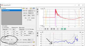
I'd like to ask how to lay out an RL circuit for this tweeter in the crossover tab.
I'm trying to shelve the response peak above 10k

This is my circuit so far

When I add an RL circuit in WinPCD I can flatten the curve like this:

PCD is unclear to me when showing the RL in the schematic and I don't know how to do the same thing in Vituix.

Can anyone help? Thanks!
I'd like to ask how to lay out an RL circuit for this tweeter in the crossover tab.
I'm trying to shelve the response peak above 10k
This is my circuit so far
When I add an RL circuit in WinPCD I can flatten the curve like this:
PCD is unclear to me when showing the RL in the schematic and I don't know how to do the same thing in Vituix.
Can anyone help? Thanks!
Member
Joined 2003
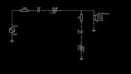
Ah, great, thanks. But this is an inductor in series with massive DCR. How does one include a separate resistor to do the same thing? Put it in parallel with the inductor?
Member
Joined 2003
Hello,
are there any specific requirements related to measuring and exporting using REW? Any particular issues with phase to be wary of?
Thank you for the software.
are there any specific requirements related to measuring and exporting using REW? Any particular issues with phase to be wary of?
Thank you for the software.
Member
Joined 2003
- Home
- Design & Build
- Software Tools
- VituixCAD