Another constraint that might be useful is to set a minimum resistance of each coil.
Coils are ideal, and series resistor includes also internal resistance of the coil - just like in LspCAD 5.25. Resistor is not dedicated only for the coil.
Anyway, all parameters have minimum and maximum limits inside the program. These constraints prevent both user and optimizer to set for example negative resistance values. It's possible show and let user to modify min and max, but usually it would be just repeating disinformation and extra columns in parameter list.
I would optimize few times. First run without limits, and next rounds with coil resistances locked. Value locked to minimum with reasonable price if optimized was zero, etc. Multiple rounds is needed anyway because optimizer won't give standard (E12, E24) values. Yes, that is also doable, but could interfere solving. I will test how it works.
Last edited:
1.1.22.0 (2017-12-18)
- Undo (Ctrl+Z) command added to context menu of filter schema.
Saves up to 10 last crossover changes and situations before parameter adjustments. - Show target checkbox removed from SPL Target window.
- Apply button removed from SPL Target window.
- SPL Target window renamed to Optimizer (Ctrl+T).
- Filter gain of driver selection added to Optimizer.
Optimizes filter response (amplitude only) of currently selected driver to overlay curve in Filter chart. - Minimum impedance target added to Optimizer.
Squared error increases if impedance drops below the setting.
Minimum is detected from total impedance while optimizing axial and power responses.
Minimum is detected from impedance of selected way while optimizing axial response of way or filter gain. - Passive component snap (No, E12, E24, E48) added to Optimizer.
Rounds to closest value in selected E-series when optimizing is done. - Seek level checkboxes added to Optimizer, for axial and power responses.
If checked, response is optimized to both slope and level of magenta target line.
If unchecked, optimizer does not care about level - just slope within range of target line. - Optimize Gain and Delay checkboxes added to Way settings.
If checked, optimizer is allowed to modify "active" gain and delay of way.
Saved to project file (vxp) for the next session. - Undo button added to Optimizer.
Same function as Undo in filter schema.
Does not undo gain and delay of way. - Show minimum phase command moved from View menu to context menu of SPL chart.
- Show excess phase command moved from View menu to context menu of SPL chart.
- Show excess group delay command moved from View menu to context menu of GD & Phase chart.
- Show target line command added to context menu of SPL chart.
- Show normal phase command added to context menu of SPL chart.
- Show target line command added to context menu of Power & DI chart.
- Show normal group delay command added to context menu of GD & Phase chart.
English manual updated including new features in rev. 1.1.22.0.
German translation is valid for 1.1.21.0 but will be updated - sooner or later.
German translation is valid for 1.1.21.0 but will be updated - sooner or later.
I have been trying out your software and just wanted to say thank you for making such a great peice of work available free.
I have previously worked with many speaker packages including Leap (which is incredibly difficult to set up and use), Lspcad, Speaker Workshop ( which is practically user unfriendly).
Your’s is rapidly becoming as comprehensive as Leap and better in some respects but remains very approachable and easy to start using. As I dont work in the industry any more I no longer have access to Leap and it is great to have a comprehensive simulation tool available again even if it is only for my home projects.
Many thanks, Andrew
I am guessing, but I think he might have meant it would be useful to be able to make the trace tool follow a specific colour. That way it would be easier to exract the different rotations traces.
However its not that hard to make it track along a specific trace by clicking at appropriate points so I don’t think its a big problem.
Andrew
However its not that hard to make it track along a specific trace by clicking at appropriate points so I don’t think its a big problem.
Andrew
aczern, sorry that I'm quite narrow-minded sometimes - maybe always 🙂
SPL Trace has been mostly programming challenge for me. It's not necessary part of the program because traced curves should not be used in simulation other than very rough preliminary design. Smaller reason is that older tools such as SPL Copy and SPL Tracer are not so excellent, and people should have some working tool (though my attitude for tracing is negative). Any publishing features would be total overkill.
Thanks Andrew! Leap is - or was? true pro tool. I have not resources and brain for that level. I'm just trying to include all features common diy designer could need, and leave driver's cone/motor design, material FEM, room acoustics etc. out. It is the league where I play, though at the moment I design more commercial speakers than diy for myself.
Last edited:
I am guessing, but I think he might have meant it would be useful to be able to make the trace tool follow a specific colour.
It has color tolerance which separates e.g. blue and green curves while tracing. Tolerance is +/-30 (of 360) degrees.
New video lesson: VituixCAD Optimizer
Someone may wonder why I remove excess delay by setting negative delay to drivers. In the video beginning at 2:08. The reason is that phase unwrapping for group delay calculation fails at very high frequencies if excess delay in the measurement exceeds about 460 microseconds. Unwrapping fails when phase wrapping is more dense than density of internal frequency range i.e. 48 points/octave.
Another problem is that group delay curve is not at 0 ms line at any frequency as it should be in order to read (excess) GD directly from the chart.
Simulation of frequency responses could also fail if excess delay is very long because complex summing of responses fails.
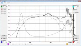
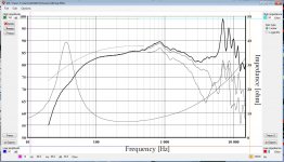
Symptoms with excess delay of 465 us (160 mm).
An externally hosted image should be here but it was not working when we last tested it.
Removing of small excess delay is not mandatory but recommended. Removing is mandatory if frequency responses are measured with REW (in single channel mode) because timing reference of exports is at the microphone - not on the surface of baffle or close to acoustic center of the driver.
Excess delay can be removed in ARTA with PreDelay setting while exporting responses for the simulator, but procedure is not simpler than with VituixCAD.
Hello,
I'm having trouble with the SPL Trace tool.
When I paste the image it's always bigger than normal.
I also can't enter a new value to the fields that define the boundaries.
Any idea why this is happening?
I'm using windows 7.
Best regards,
George
I'm having trouble with the SPL Trace tool.
When I paste the image it's always bigger than normal.
I also can't enter a new value to the fields that define the boundaries.
Any idea why this is happening?
I'm using windows 7.
Best regards,
George
Attachments
^Looks like some issue with window size detection. Try single display mode if you have dual display.
Windows 7 should be sp1, both 32-bit and 64-bit okay.
VituixCAD is designed for .NET Framework 4.0 or later. The following .NET Frameworks can run the program per Microsoft:
.NET Framework 4
.NET Framework 4.5
.NET Framework 4.5.1
.NET Framework 4.5.2
.NET Framework 4.6
.NET Framework 4.6.1
.NET Framework 4.6.2
.NET Framework 4.7
.NET Framework 4.7.1
Try to check which version you have:
How to: Determine Which .NET Framework Versions Are Installed
For example I have Windows 10 Fall Creators Update and .NET 4.7.1:
HKEY_LOCAL_MACHINE\SOFTWARE\Microsoft\NET Framework Setup\NDP\v4\Full\Release = 461308
Could you try to install .NET 4.6.2? That was working perfectly at least on Windows 10. Another trick could be trying Classic theme which is still available in Win 7. Unfortunately I don't have Win 7 machine anymore and cannot repeat the error here.
Someone had this kind of problem with SPL Copy which is also .NET application. Probably the same issue with WinAPI - NET interface.
Someone had this kind of problem with SPL Copy which is also .NET application. Probably the same issue with WinAPI - NET interface.
For the time being I sidestepped the problem of not being able to see what the actual boundary values are, by putting the cursor in the relative box, hitting backspace three times and entering the correct value of impedance, for the lower and higher boundaries.
That trick gave the correct value of impedance, even though I can't see the actual values entered.
Best regards,
George
P.S. I installed net version 4.7.02558 release 461310 without being able to resolve my problem.
That trick gave the correct value of impedance, even though I can't see the actual values entered.
Best regards,
George
P.S. I installed net version 4.7.02558 release 461310 without being able to resolve my problem.
Last edited:
Found the reason of the problem.
I had set the font size to medium (125%) so I could better read the characters on my monitor screen (I'm 53 years old).
Once I reverted to small font size (100%) everything is working perfectly again.
Thanks a million for your help and wonderful software.
I had set the font size to medium (125%) so I could better read the characters on my monitor screen (I'm 53 years old).
Once I reverted to small font size (100%) everything is working perfectly again.
Thanks a million for your help and wonderful software.
Very good! I was just beginning to write that you should test application scaling if that feature exists in your system. Scaling happens to work on Windows 10 with SPL Trace, but not tested on 7.
Generally, VituixCAD is neither designed nor tested for scaling >100%, and therefore errors could occur. Situation could be better in the future. I'm quite sure that can be improved by changing some parts in the program.
Generally, VituixCAD is neither designed nor tested for scaling >100%, and therefore errors could occur. Situation could be better in the future. I'm quite sure that can be improved by changing some parts in the program.
gagnou,
Could you test this revision, is SPL Trace working on Windows 7 with 125% scaling or not?
Auto scaling of all forms is switched off, but no difference to official release at least on Windows 10 (both work fine).
Could you test this revision, is SPL Trace working on Windows 7 with 125% scaling or not?
Auto scaling of all forms is switched off, but no difference to official release at least on Windows 10 (both work fine).
- Home
- Design & Build
- Software Tools
- VituixCAD