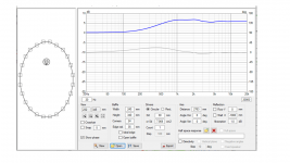
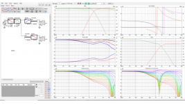
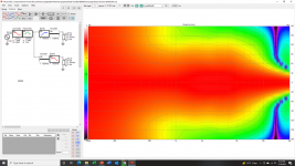
For this next sim, I wanted to explore the concept of the minimum baffle. The smallest baffle which could encompass our two hypothetical drivers. An oval shape that is 240 mm wide by 340 mm high, with 35 mm edge radius or bevel, is just big enough to accommodate a 105 mm flange tweeter and a 165 mm frame woofer.
An oval shaped speaker cabinet would not be easy to build. The baffle itself would not be too hard to make with a band saw and a router, but the oval-profiled cabinet behind the baffle would be challenging. It is not really a practical cabinet. I am showing this sim as a comparison to the rectangular and trapezoidal baffles in the prior posts, not to promote it as a viable option.
I found two different filters which would be acceptable here. The first is a quasi 3rd order LR, shown with a 20 mm offset between the woofer and tweeter. Anything from 10 mm to 40 mm would work, but 20 mm seems to be the best. This filter would be a good option as a target function for a passive crossover. The listening window and on-axis curves are flat. The ER and ERDI curve is flat +/- 1 dB from 500 Hz to 10 kHz. The power response and DI curve is +/- 1.5 dB from 700 Hz to 9 kHz.
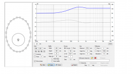
The second filter is 3rd order Butterworth. In order to hit the target curve, the tweeter Fc frequency had to be 1890 Hz. This filter works best with no offset between the woofer and tweeter, so this is a good option with an active filter, where the time delay can be optimized. The ER and ERDI curve is flat +/- 1 dB from 500 Hz to 10 kHz. The power response and DI curve is +/- 1 dB from 700 Hz to 8 kHz.
An oval shaped speaker cabinet would not be easy to build. The baffle itself would not be too hard to make with a band saw and a router, but the oval-profiled cabinet behind the baffle would be challenging. It is not really a practical cabinet. I am showing this sim as a comparison to the rectangular and trapezoidal baffles in the prior posts, not to promote it as a viable option.
I found two different filters which would be acceptable here. The first is a quasi 3rd order LR, shown with a 20 mm offset between the woofer and tweeter. Anything from 10 mm to 40 mm would work, but 20 mm seems to be the best. This filter would be a good option as a target function for a passive crossover. The listening window and on-axis curves are flat. The ER and ERDI curve is flat +/- 1 dB from 500 Hz to 10 kHz. The power response and DI curve is +/- 1.5 dB from 700 Hz to 9 kHz.
The second filter is 3rd order Butterworth. In order to hit the target curve, the tweeter Fc frequency had to be 1890 Hz. This filter works best with no offset between the woofer and tweeter, so this is a good option with an active filter, where the time delay can be optimized. The ER and ERDI curve is flat +/- 1 dB from 500 Hz to 10 kHz. The power response and DI curve is +/- 1 dB from 700 Hz to 8 kHz.
Attachments
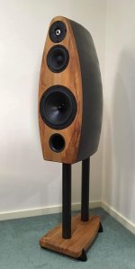
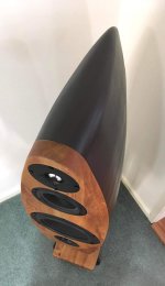
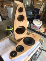
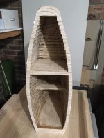
I saw an oval-ish 3 way DIY speaker build over at DIY Loudspeaker project pad group. I thought it looked really nice 🙂
Just attaching some pics from there for inspiration.. 🙂
I don't know if such cabinets will help in diffraction control (including the depth and width in addition to baffle. Intuition says it might help but I don't know for sure). From your simulation, it looks like at least the baffle shape helps. In the pic I have attached, the baffle is also minimal around tweeter. So it might also help I think.
I thought non parallel walls will help with avoiding standing waves till I saw this post:
https://www.acculution.com/single-post/037-misconceptions-in-acoustics
Edit: Just saw that in your sim the baffle looks much wider than the tweeter. So the type of minimal baffle shape in the pics that I have attached and the one that you have shown in sim might be behaving very differently. Sorry for creating the confusion.
Attachments
Last edited:
Yeah the "boring" xo sounded fine at first and the graphs looked fine, but after some listening it didn't feel quite right and noticed there is suspicious group delay in the simulation. Made the new xo to address the group delay and lo and behold, the previous settings was revealed to be "boring" sound in comparison! I don't currently have any reference speaker to compare against so it wasn't immediately obvious whats wrong with the sound. The group delay might be the main difference with the perceived sound between the xo's because there is quite much change in the filters, but I don't know. Might be some other issue as well like missconfiguration of the DSP as well why not, this is just a simulation and not measurement of the implementation 😀
The important thing is that the spinorama / rating don't reveal the difference ( assuming my DSP settings were correct on both ). The group delay is visible in the impulse response though (some ASR measurements didn't have group delay plots, but had impulse responses). Cause for the excess group delay was delay block on the tweeter, and oversight while tuning the xo. This would not be a problem with passive crossover since there is no danger accidentally use delay in a wrong place.
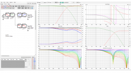
Illustration attached, can you spot the difference from the data, which one sounds better? Impulse response shows the delay on tweeter and reveals which is the worse sounding specimen, but the SPL and DI graphs don't.


I limited the graph to show >200Hz because the other one has bass boost in the simulation and the other doesn't while in the DSP the bass is adjusted by ear and is similar on both and should not affect much on the perceived sound quality.
edit. alright getting of topic, although relevant 🙂
Last edited:
@tmuikku:
I don't have any experience predicting audible traits in sound looking at the graphs unless something is too wrong. So I am not able to say which among the two configurations is better. But I am trying to deduce some information from the graphs from whatever I have learnt. Please point out any mistakes in my approach.
1) In figure-1(left side pic in your attachment), we see that the impulse response is shifted to the right by 1 unit in the graph compared to figure-2 (I don't know what units are there in the x-axis of the plots). So that points to a group delay in configuration shown in fig-1.
2) I can see that the step response in figure-2 looks cleaner. The narrow peak of the tweeter arriving first at the mic, followed by the wider peak of opposite polarity of the mid, which is followed by the even wider peak of woofer. Midrange is in opposite polarity with tweeter and woofer. In figure-1, the narrow tweeter peak is delayed compared to that in figure-2. So there is a difference in time alignment of the drivers. Instead of the tweeter sound arriving first, here the midrange sound arrives first. But I don't know how time alignment differences can be picked up while hearing music.
3) What I have learnt is the impulse response and frequency response convey the same information assuming the system is linear time invariant. But reading the overall spectral balance from the impulse response/step response (which is the integral of impulse response) is hard. So we apply the FFT and get the frequency response. The information is complete only when we have both the magnitude and the phase response. So just by looking at the SPL magnitude responses, we are reading only part of the information.
4) In the power response in figure-1, I see a minute bump in the power response in the octave of 500Hz-1kHz, compared to figure-2. I read in some other thread that power response bumps above 300-400 Hz may make itself audible as sort of brighter sound.
Thanks
Vineeth
Yeah I'm with you, there is kind of large gap in my knowledge how to bridge graphs to perceived sound. To me the graphs look really great but they don't explain the sound, or tell how'd get it even better, or in other words to direction I'd like to take the sound. I mean if the sound doesn't feel right, there is no way to see whats the problem on the "spinorama" and the rating number. Perhaps there is, for some systems that have obvious stuff showing on these graphs, but for the two examples there there really isn't that much difference.
For example the power hump at around 600Hz you noticed can be affected by the mid driver gain somewhat, but it doesn't fix the weird feeling on the sound if I remember. I mean the magnitude of difference on the graph is about 1dB, attenuating the mid 1dB makes difference but doesn't quite fix "something is wrong" feeling. I didn't test this just now but trying to remember how I've felt during the million DSP tweaks by ear I've performed to the system, some tweaks aren't audible until many dB boost / cut. I guess the "boring" is mostly due to the timing / integration part in this case. The tweeter has a delay block, and it shows in the step response the tweeter starts playing bit later than the other drivers who start the ramp earlier.
All this is not obvious from the polar graphs or from the power and DI graphs, or the listening window and what not. And as I said perhaps this is a no problem for most people and systems, perhaps no-one else tunes their xo's without remembering to check the impulse /step response 😏 Anyway, all right lets move on.
The oval baffle in my sim is just barely large enough to accommodate the typical 100 mm flange of a tweeter AND the required 35 mm edge radius. Once the edge radius is taken into account, the actual flat baffle area is actually quite small. The oval cabinet you are showing has a much smaller edge radius (looks like about 5 mm), so the baffle outer dimensions can be quite a bit smaller of course. There is a significant downside to hard edges in my opinion. They create high frequency diffraction which, in my opinion, damages the stability of the three-dimensional illusion.Edit: Just saw that in your sim the baffle looks much wider than the tweeter. So the type of minimal baffle shape in the pics that I have attached and the one that you have shown in sim might be behaving very differently. Sorry for creating the confusion.
There are tweeters available with reduced flanges in the 50 mm to 75 mm range. This would give the designer more options. I am choosing to limit my examples to a 165 mm frame woofer and a 105 mm frame tweeter.
Very interesting discussion about group delay in the midrange. Several months ago, Headshake and I were having a discussion, and he pointed out the importance of minimal group delay from 200 Hz on up. Of course, some GD is anavoidable below 100 Hz, and all of my focus on GD up to that point had been in the low frequencies. But he clued me into this.
I believe that with typical passive crossovers on a typical flat baffle, it would be hard to get a GD issue in the crossover region. But with active systems and DSP based crossovers, there are many opportunities to accidently screw up the sound in some way. The GD measurement is a good way to catch it.
j.
To summarize the results from the last three simulations:
Trapezoidal baffle in posts 111 and 115
Rectangular baffle in posts 120 and 121
Oval baffle in post 161
The directivity performance of all three cases is very similar. The trapezoidal baffle has a very slight performance edge. The rectangular and the oval baffles are roughly equal. The added complexity of oval baffle is definitely not justified on the basis of the directivity performance, and the trapezoidal shape is probably not justified either. However, the trapezoid is just slightly more complicated to build than a straight-up box.
j.
That may be true within the limits of these simple simulations and constraints, but in practice (or with a more sophisticated simulation), angled facets and a non rectangular shape can be quite beneficial to getting a smooth directivity response even more so if a waveguide is not used for the tweeter.The directivity performance of all three cases is very similar. The trapezoidal baffle has a very slight performance edge. The rectangular and the oval baffles are roughly equal. The added complexity of oval baffle is definitely not justified on the basis of the directivity performance, and the trapezoidal shape is probably not justified either. However, the trapezoid is just slightly more complicated to build than a straight-up box.
So it appears I may be bumping into the limits of the VituixCad diffraction simulation. Well, this was fun while it lasted 😉
I'd say 500hz to 5000hz with no large shifts in the GD is a good thing. A gradual rise up or down is ok too, just no small humps in the positive or negative that are larger than -/+1ms. The kicker is the baffle edge messes with the GD.
Here is the paper on group delay:
https://ieeexplore.ieee.org/document/9450008
Here is the paper on group delay:
https://ieeexplore.ieee.org/document/9450008
The listening test contained four different signals: the unit impulse, the pink impulse, a castanet recording, and a synthetic hi-hat cymbal sound. The two former signals are known to be the most critical for group-delay audibility, whereas the latter two resemble real-life musical signals and thus help to generalize the results better. Group-delay audibility was tested at the frequencies 500 Hz, 1 kHz, 2 kHz, 3 kHz, and 4 kHz. The results indicate that the audibility thresholds for local group-delay variation are less than ±1 ms for the most critical signals, and approximately 1.5 ms to 4.5 ms for a local positive group-delay peak and between −1.0 ms and −2.3 ms for a local negative group-delay peak for real-life signals.
No activity in the thread for long time so I'll post some screenshots and thoughts about the diffraction hump even though these are not from VituixCAD. I've been wondering every now and then what actually makes the main diffraction hump but never kind of got the aha moment for it until recently was trying to get idea how much sound goes around speaker box and did some ripple tank experiments.The challenge the the hump presents to us is that it very real in the on-axis response, but it starts to disappear beyond 30 degrees, and by 60 degrees it is pretty much gone. So if you EQ the hump out of the on-axis response, you have now created a dip in the off-axis response... which probably means a dip in the room response, power response, and ER curve.
Tmuikku - your sims are interesting. I think we need to be cautious in drawing big conclusions from the sims of drivers centered in square baffles. It is well known that a driver centered in a square baffle is almost a worst case scenario. For instance, here is your 8" baffle with 1" tweeter sim, but with the tweeter moved up a bit. If I moved it horizontally, I could get it even smoother.
View attachment 1005737
Very interesting discussion. Thanks !
j.
Here is few observations:
Extreme test here, diffraction at end of an wall, see top part of the image. Demonstrates that the diffraction at the edge is sound bending around the corner but at the same time a "backwave" emerges, with opposite polarity. This is clearly seen here with ~1 wavelength sound pulse, waves both side of the wall are in opposite polarity. Test it here at ripple tank

Now imagine this happening at the edge of baffle whose width is 1 wavelength and the driver is at the middle. Now there is 1/2wl distance (delay) from driver center to edge and there a new sound source emerges with opposite polarity making another 1/2wl. Direct sound and diffraction "back wave" combine constructively at listening position as they are in phase, creating the great diffraction hump. The hump is about exactly centered the baffle width wavelength on your example supporting this (also here and perhaps on any of the sims on this thread, and others?). Why it mellows out toward off-axis because there is no "back wave" there arriving bit later and summing with the direct sound to show up in frequency response, only the original wave seems to be there. In the picture, if the listener was on the left side of the screen and up was 90 degrees off-axis the diffraction hump would probably extend to about 45 degrees where the backwave joins to the main wave. Don't get distracted by the weird setup, important bit is the pointy tip top of the image and seeing the "back wave" from diffraction.
And while at it another observation,
this is basicaly from what mabat posted in ATH thread, some full enclosure polar responses with and without roundings both on front and back edges along with some various depth enclosures. Back corners seem to affect a lot and some of the sound seems to go around the box. Some effect seems to happen when the front edge diffracts, then attenuated wave goes around the back and phase flipped "backwave" leaves towards listener. This is easily millisecond or two delay on all speakers (depth of the enclosure), perhaps more. To make it approach delays of first room reflections make the enclosure 1m deep 😀 Not very practical.. But, due to fact that the "back wave" is opposite polarity one could perhaps make triangular cabinet with pointy edge at the back, where sound traveling along both sides of the enclosure would diffract at the same time. Then, part of the sound would cancel out as the wave goes around the edge and rides along with the opposite phase one from the other side. See here, if the box back wall has width to it diffracted wave from the back corner inverts in phase (now white) and a black one follows it, which is in-phase that went around the enclosure from the other side. Ripple tank

Yeah fine idea but these don't seem to cancel completely, because the "back wave" is not at same amplitude as the original sound (that came around the bend from the other side). Some residual black wave left as seen here on the next image, but the white is about gone. From this I suspect there is more sound going around the box than reflecting back from a back corner along same side. Make circumference of the enclosure about two meters to add enough path length for these not to arrive before first room reflections 😀 Yeah. Well, pointy back seems to work nice, reduces some effect of the enclosure back corner.

Third one, from the first experiment, and then you see it from the others as well.
Diffraction ripple that shows off-axis is not from the closest side corner but from the opposite side corner! This made me realize the diffraction is entirely time problem, we just inspect if mostly in the frequency response. Diffraction would be fine if it boosted the response like the diffraction hump off axis, when direct sound and diffracted sound sum in phase. But his is only the case to particular direction and at particular frequency (small bandwidth).
See for example the last triangular enclosure experiment. The first wave (wave front) is nice to all directions followed by the ghostly white back wave due to edge diffraction, which then sums up with direct sound at various delays at various angles and causes interference pattern on a frequency response. If you look at the ghost as a circle and zone in to its center point you'll notice it is kind of the opposite corner of the box, which then causes problems inspected from other side of the box, delayed sound which shows in frequency response as well. The corner that is towards the observing point would not make much audible difference because it is almost in phase with the direct sound (diffraction happens at the same time as direct sound, inspected from the same side). Imagine your self on the left side of the image, the ghost you'll perhaps perceive came from the right side of the enclosure, the diffraction back wave!
Another related to the same phenomenon, enclosure features at the opposite side of observation point that cause problems towards the observation point:
See on the middle image, the deep box example, how the white part of the wave pulse the positive (white) amplitude is a lot wider to sides than towards the listener (up)? This is due to the driver, sound emanates from both sides of the driver and at this particular frequency they sum up about in phase but if observed at left, 90 degrees to side, it is smeared in time, widened, due to the fact that sound from the close edge of the driver arrives first before that of the further edge. If you'd make the frequency higher you'd observe beaming happening, opposite sides of the driver have path length difference and could sum destructively observed from the side / back.
Anyway, nice phenomena to think about, brain twister. Anything one does in ripple tank the ghosts don't disappear.. Unless using point source (which doesn't exists, or does it?🙂 and no enclosure, which doesn't exists either. Perhaps if one wants to avoid this the "back reflection", just crossover to a smaller driver below these things appear, longer wavelengths than the baffle (or circumference of the box) don't show these issues since the wavelength is so long it pretty much sums up all around as constructive interference. If one wants to minimize all this, minimize the structure relative to wavelengths it is used for. Next best thing would be to make the structure a sphere and worst thing would be = don't mind about it.
Last edited:

I wonder what would happen if you covered the back of the cabinet with 2-4" of open cell foam or similar? Might make chamfering/rounding the back edges moot.
Intuitively it should reduce sound going around the enclosure and help with the issue, well worth experimenting I'd say. But, gotta remember I have no idea how audible all this is. Perhaps it is something that could be used as last minute tweak, perhaps sell in the Snake Oil market with high price tag, a retrofit. Not sure if it would sell any if there is actual measurable difference and improvement to sound 😀
Last edited:
I'd say 500hz to 5000hz with no large shifts in the GD is a good thing. A gradual rise up or down is ok too, just no small humps in the positive or negative that are larger than -/+1ms. The kicker is the baffle edge messes with the GD.
Here is the paper on group delay:
https://ieeexplore.ieee.org/document/9450008
Interesting article. I found this statement most interesting (for those of us who listen to loudspeakers instead of headphones):
"In well-designed loudspeakers, the group-delay variations can be designed to be small, but when loudspeakers are used in rooms, the group-delay variations can become substantial, up to several tens of milliseconds."
Thanks for the information tmuikku -
I have not posted to this thread in a while, but I have not given up. I am seriously taking the advice of both Fluid and Kimmo. I am building some foam board prototypes of various baffle shapes. I want to understand exactly what a faceted baffle does (Avalon-style), and how to approximate the response with VituixCad simulation. As you know, VituixCad models a fixed edge radius... If you tell it 25 mm radius, it applies it to all sides of the baffle. A faceted bevel is variable, so VituixCad can not simulate it precisely. But there may be ways to get a "good enough" simulation.
j.
hifijim, I am messing with pink foam baffles too. I have it all over the floor (btw serrated blades > razor blades for cutting.. don't know what you are using but i just discovered this) Be sure to keep posting the progress because I am designing a baffle right now.
My baffle has a 44mm edge radius and I can remove it. So I took measurements with just the L/R sides, L/R/T sides, and all sides. Notice the GD shift. I find the speaker harder to locate and airier with the rounding.


My baffle has a 44mm edge radius and I can remove it. So I took measurements with just the L/R sides, L/R/T sides, and all sides. Notice the GD shift. I find the speaker harder to locate and airier with the rounding.
Nice, nothing beats good old prototyping 🙂
FYI not sure if you fellows already checked out but Mabat published multiple series of small enclosure BEM sims with and without roundovers both on the front and back of the enclosure. Additionally there is few sims that shows difference with box depth. Look here and read on, there are multiple sets.
All of that is missing in the VituixCAD diffraction tool of course, like been told by fluid and AllenB at least, many times 😀 The effect of back corners / box depth seems dramatic although it is only few decibels here and there. There is still a difference though, which might matter. As you are measuring diffraction of baffle slants / facets in order to understand and eventually better the whole system performance you should definitely checkout how the whole box measures and hook the baffle to a box as you measure.
Mabat hinted he is going to publish new script soon that would generate boxes like that, ready for BEM simulation in ABEC. It doesn't probably have slants in the algorithm since none has been demonstrated yet but at least you could experiment with the box depth and what relation there is between baffle / box dimensions. This would perhaps give insight what size box works better than some other size for slanted baffle as well.
Last edited:
Hi, if I'm not completely misunderstood kimmosto talks about that "the baffle shouldn't narrow woofers response below crossover", and this is practically due the diffraction hump if I'm not mistaken (or too high crossover or the woofer). Boost by diffraction on-axis equals narrower directivity. The advice is to prevent hump in DI around crossover which is due to woofer having narrower dispersion than tweeter around the crossover frequency. I think this is exactly same issue as you mentioned earlier on this thread that the diffraction hump makes difficult crossover.Thanks for the information tmuikku -
I have not posted to this thread in a while, but I have not given up. I am seriously taking the advice of both Fluid and Kimmo. I am building some foam board prototypes of various baffle shapes. I want to understand exactly what a faceted baffle does (Avalon-style), and how to approximate the response with VituixCad simulation. As you know, VituixCad models a fixed edge radius... If you tell it 25 mm radius, it applies it to all sides of the baffle. A faceted bevel is variable, so VituixCad can not simulate it precisely. But there may be ways to get a "good enough" simulation.
j.
Alright I guess there are few things that you could do. Use as narrow baffle as possible, and go with smaller woofer in order to get the diffraction hump up in frequency so that the crossover can be below this. Does this sound reasonable? You could widen the baffle to move the diffraction hump down but this would also narrow the woofers response.
Or, you could perhaps try lessen the diffraction hump. If my reasoning is correct in post #173 that the hump is from the front edges being one wavelength apart, woofer in the middle, edge diffraction back wave summing in phase on axis that makes the hump on-axis. Now, you could try to utilize back side of the enclosure to introduce diffraction "back wave" to the sides as well in order to make the hump directivity wider. Or perhaps if there was opposite phase backwave towards center to just cancel some of the hump away.
Not excatly sure if and how this would work out but from the simple ripple tank tests here is some. It is quite hard to get the exact levels by eye 😀 But something one could experiment with in BEM or prototyping. Not sure if any of these shapes solve the issue, but perhaps something else would.
Following tests are all 1wl long sound pulse, 1wl wide baffle with ~1wl transducer on it. Alright, 1kHz, ~12", 34cm wavelength. This is middle of the diffraction hump, the problematic boost on axis that narrows directivity.
Here is attempt to see if 0.5wl, 1wl or 1.5wl deep box would generate some diffraction from the enclosure back, curing back waves? The first 1/2wl deep box example looks like it has about as thick wave front going to the sides as to the front in total. The deeper boxes seem like a mess especially to the sides and looks like there is gonna be some cancellation, thicker stuff going to front and mess to the sides. Not sure what to think about it yet, perhaps need to tune in the ripple tank parameters to see better, or use probes or something. We have BEM sims on similar situation in mabats ATH thread, need to check them out again. Ripple tank links 0.5wl - 1wl - 1.5wl


Then, a pointy back where the other side partially cancels the other side diffraction back of the enclosure and vice versa. Wow, looks clean in comparison to the others! And it looks like the on axis diffraction hump would be smaller or smoother at least, thick clean stuff going to the sides as well, perhaps little wider directivity. Ripple tank

It looks like bit of a box with pointy bit on the back makes a bit more sound to 90 deg, perhaps even more smooth diffraction hump? Certainly cleaner output by the looks of it, cleaner than in the first image without the pointy back. Ripple tank

It looks like the pointy back doesn't have to be exactly pointy. about 1/4wl flat part is fine, 1/2wl seems to be the limit for "cancellation". This wold change with frequency but we are looking at frequency middle of diffraction hump and plan to crossover below it or at least as low as possible. I guess one could have round on the back. Perhaps this is why the "tear drop" style enclosures that are narrower on the back than on the front work nice, they smoothen out the diffraction hump!? (perhaps, BEM required to see). Ripple tank 1/4wl - 1/2wl


What you just read was attempt to reduce effect of baffle edge diffraction by utilizing diffraction on the back of the enclosure, and by the looks of it this could work at least on some frequencies, at least the odd number of box corners where one at the back and is diffracting sound form both sides simultaneously makes better looking ripple tank wave than any of the square boxes. Seeing is not hearing, hopefully someone pops in with BEM results 😀
ps. on ripple tank some of the settings are not part of the URL. Adjust color scheme 4 and Brightness to 955.
Last edited:
- Home
- Loudspeakers
- Multi-Way
- VituixCad Simulations with Ideal Drivers