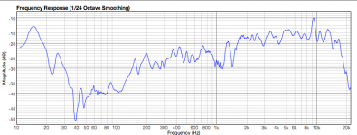
Obviously the value for the capacitor should be chosen smaller to adapt the B200 better maybe even a smaller coil value (like 100nF and 80mH instead of the 150nF and 100mH that I use right now...), as a matter of fact I tweaked the filter today to adapt better to my Monacor SPH-30X 3" fullrange drivers.
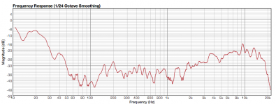
Here's a measurement with the old filter:
Here's a measurement with the old filter:
Attachments
I know it looks kinda bad, but in real life this configuration sounds very good. The drivers would measure a lot better in a proper enclosure. But I made a very small (1 liter) enclosure to produce stereo sound for portable use (so no hifi quality was aimed at)... With the filter installed the midrange area was very nice and the bass and higher frequencies much better, the latter even better audible from a larger distance.
After the tweaked filter is finished I can show the difference...
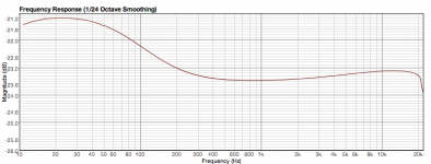
Here's how it measures without filter:
After the tweaked filter is finished I can show the difference...
Here's how it measures without filter:
Attachments
Hey v-bro, it don't look to bad for a mini system. What would be interesting to see is a transient test at the null freq. There may be enough R there to damp it, but then that increases time delay.
One thing I like to avoid is LC combinations, and stick to C only, ie a twin T filter. No tuned circuits to excite.
Also, I don't place too much weight on FR graphs. OK for before and after comparisons, but unless you compensate for room effects and calibrate the entire kit regularly who knows what your results will / should be. In the case of the B200, I only had the published data and Joes ears to go by.
If I notice a problem, I'll take measurements to identify the problem, make changes, and listen. Taking measurements at that time only proves (or disproves!) you know your stuff. Doesn't mean you have cured the problem. That's why I haven't asked anyone to do FR graphs. It's THEIR ears that must be happy.
I'll might have a look at your driver later, see what I can come up with, just for fun. As they say, 2 heads are thicker than 1.
Geoff.
Hi Geoff,
I also like to avoid LC speakerfilters, that's why the line level RC filters caught my eye. I only follow my ears in this game and measure afterwards, sometimes discovering my ears didn't analize very well, sometimes they do. But basically I go for the sound my ears most like to hear.
It would be nice if you could come up with another approach, other ideas have been very revealing before. So thanks in advance!
OK, lets get back to the B200. Who hijacked that any way. Whoops, I did it again.
Going on some of the comments made, I suspect something is happening as a bonus.
The cap that provides the high freq boost will give a phase shift as it comes into effect. The current through a capacitor leads the voltage.
It could be compensating the phase as the HF leaves the apex of the cone, bringing it into line with the midrange.
That falls into line with some of the comments.
If anyone is interested in doing a FR graph with the phase plugs and minus the filter, we can optimise the filter to use with the plugs.
Cheers,
Geoff
My filter is still going strong,, ran direct to compare & ran for the haywire mess of my circuit & put in back in. Time for me to put in in some small project boxes.What I got going on looks down right scary...
Why not mount the components on a tag strip, and mount inside the amp. Less plugs and sockets, less cables.
Good idea reverting back to the pre filter days. How long did run without the filter?
Regards,
Geoff.
Good idea reverting back to the pre filter days. How long did run without the filter?
Regards,
Geoff.
I ran it for just one song,all I needed to hear..With a good pre as my 27 is, this filter is a dream with it.I lack nothing & the mids are just a delight & can listen till I drop..No fatigue & no percieved lack of life or dulling which is quite strange because that is what happened with every passive after amp filter I used. Good idea about the tag strip, I run the circuit as this.
.01uf Vitamin Q leading the pack for 150hz 6db HP & then the circuit as 180pf-.0027uf-220pf & resistors set for a 100k amp. Then a ribbon in rear fire mode only @ 10k 1st order w/ no padding. results are best I have had to date sonicaly with B200. Amp is a 300B PP for 22w. BASH active plates set @ 150hz 4th , driving the Vifa M26wr-09-08's. all on same baffle. Can I install the circuit in my 27 preamp..?

.01uf Vitamin Q leading the pack for 150hz 6db HP & then the circuit as 180pf-.0027uf-220pf & resistors set for a 100k amp. Then a ribbon in rear fire mode only @ 10k 1st order w/ no padding. results are best I have had to date sonicaly with B200. Amp is a 300B PP for 22w. BASH active plates set @ 150hz 4th , driving the Vifa M26wr-09-08's. all on same baffle. Can I install the circuit in my 27 preamp..?


"Can I install the circuit in my 27 preamp..?"
Yep. In terms of cable capacitance, may be better in the main amp.
Depends where you have room. Anywhere other than the birds nest on the table has to better.
Geoff.
Yep. In terms of cable capacitance, may be better in the main amp.
Depends where you have room. Anywhere other than the birds nest on the table has to better.
Geoff.
Anywhere other than the birds nest on the table has to better.
That is exactly what I have to....*s* Not insulated or nuttin...living dangerous or just plain stupid I would say, I'll go with stupid.!!!!!!!!!!!!!!!!1
And on top of that it's noisy, the circuit functions as an antenna for all kinds of static that's on the air....
Even if your ears can't hear it, your components might still get stressed by it....
Even if your ears can't hear it, your components might still get stressed by it....
Have to admit I also experiment that way first (to determine the neccessary components and their size) , but in a shielded perimeter my ears most of the times can even tell the difference.
Most low component count circuits I place in a separate box first (to experiment with) and if they're a good add-on to another circuit and providing it fits in the enclosure of that circuit I build it inside....
It gives the advantage of:
-Being able to modify the original circuit at a later date without having to open the amp up all the time.
-Compare to the original in the amp again after modification.
-Using it as a temporary add-on to other systems.
I just like to experiment....😀
"your components might still get stressed by it...."
Ah.., he's using valves, not 3 legged fuses.
And long may they glow into the night.
Ah.., he's using valves, not 3 legged fuses.
And long may they glow into the night.
Geoff H said:Hi Guys,
This includes the low cut filter. 6dB /octave, -3dB at 100 Hz. This points out another advantage of doing things at line level. Low pass at 8ohm requires a huge cap, which wouldn't work due to the rising Z at resonance. It could have a reverse effect.
Any preamp worthy of the name should be capable of driving this, otherwise interconnect cables would swallow all the treble.
Cheers,
Geoff.
Geoff,
I have been most of the information on this post regarding the B200 but this filter is confusing me. Is it possible to implement this circuit/filter if one only has an integrated amp? I'm trying to cut off my B200 at 100hz and add either the Alpha 15 or Beta 15.
John
Hi John, if you have pre out - main in links, that's where it can go. Failing that, build it into the amp, infront of the vol control. That's an issue if you have different speakers on A-B out. May need to be able to switch it out.
If you have a circuit diagram of the amp, I'll have a look. I don't think your one your own there.
Regards,
Geoff.
If you have a circuit diagram of the amp, I'll have a look. I don't think your one your own there.
Regards,
Geoff.
Geoff H said:if you have pre out - main in links,
If you have a tape loop it should work there as well.
dave
Geoff H said:Hi John, if you have pre out - main in links, that's where it can go. Failing that, build it into the amp, infront of the vol control. That's an issue if you have different speakers on A-B out. May need to be able to switch it out.
If you have a circuit diagram of the amp, I'll have a look. I don't think your one your own there.
Regards,
Geoff.
Geoff,
I ok with the woodworking part but still trying to learn the electronics end. Just to clarify exactly how to install the circuit -
On the line in side - common is negative
- the leg at 0.018uf - positive
Input R of amp- top + and bottom - (does this go into the input of the amp? on just the right channel?
Sorry if these questions sound dumb - just trying to picture (in my mind) either end of the circuit and what they connect to.
John
ps: I will be testing it on an older Adcom preamp/amp system before I use it on something better.
- Status
- Not open for further replies.
- Home
- Loudspeakers
- Full Range
- Visaton B200 - Taming the shout