johninCR said:BTW, Dave I picked up a used pair of 167's that have your phase plugs. Will those fit a B200, since it has the same VC diameter?
Not really. A 1" VC with whizzer requires a smaller diameter plug than if no whizzer. The B200 plugs are also longer.
dave
Attachments
I have used the B200 myself in a commercial design. I cured the top end by putting a 0.3mH coil in series with the driver and an R-C network in parallel before the coil to bring the impedance down again.
Ricky.
Ricky.
Geoff H wrote
Hey,
Doing the correction at the line level is an interesting solution. Is there a way to make the filter suitable to a 50k (or 20k) input? (There is too much I still don't understand about LL circuits.)
Thanks,
Scott
The circuit is designed to run into a 100K load
Hey,
Doing the correction at the line level is an interesting solution. Is there a way to make the filter suitable to a 50k (or 20k) input? (There is too much I still don't understand about LL circuits.)
Thanks,
Scott
This is not a substitute for phase plugs or any other worthy mod to the driver. It is an alternative to cutting. We should always endeavour to solve these sorts of issues where the problem starts.
That's why I don't try delving into the electronics side. I leave that to you experts, and stick to exploring the mechanical side. With OB's there's plenty of room to explore, which is quite rewarding.
"I got picked on for no graphs by telling too much of what my ears tell me"
That's a shame. It's the ears that count the most. Why do many not trust them? I look forward to seeing Johns double sided horns, with or without graphs.
Listening to music, moving around in the room, and sweeping through tones with 1hz increments around problem areas may not tell the whole story, but I think it paints a better picture than any other method. Sure our ears/brain can be fooled, but they are incredibly sensitive with highly evolved and flexible data processing. I'm anxious to measure only as a test of my tuning by ear, and to generate FRD's to import into my active EQ/XO software to eliminate the guesswork. Plus there are some instances where measurements will prove helpful.
Hi JohninCR,
I've mounted my B200 in a front horn (200Hz cutoff or so). The throat was around 4.5". I got a boost (2-6db) between 200 to 900Hz and attenuation (1-4db) from 1000-6000Hz and flat after that. Spacing between driver and mouth changes the balance. This is not an exact science. If I knew how to balance the boost/attenuation I'd really be happy.
I'm not surprised you are getting great results with your waveguide. It almost looks like the front loading section of the Tannoy Autograph.
I'd like to construct those waveguides. If you don't mind, I'd appreciate it if you could post details on the construction of the waveguides (dims, process, and caveats). Thanks.
Ultrakaz,
I'll be sure to share everything, probably more than some want, because I tend to fully explain things. I need to get them to finished form, and once I get something I can listen to my work pace typically slows to a crawl.
These are different since I need to get to finished form before filling voids with sand, which I believe will have a marked improvement. Despite using doubled up real 2"x4" solid laurel to construct the terminus roundovers, the roundovers vibrate a lot, but the relatively thin plywood panels forming the waveguide are quite dead. I may not fully understand the cause of vibration, but I do know 40-50kg of sand per speaker will cure it. I've always wanted some really massive OB's anyway, so this is my chance.
Also, I want to include enough of the science, so others understand it in hopes of furthering the design through technical or aesthetic (esp size) improvements.
Impedance scaling. For a 50 K ohm input amp, halve the Rs, and double the Cs. 20K, 1/5 the Rs, 5x Cs.
There are several advantages in LL eq. The amp, be it tube or SS is in direct connection with the VC. There is less chance of ringing and other issues. Reactive components reflect back through transformers, placing strange load conditions on the plates.
Another advantage, the slew rate requirements of the amp are reduced if we are shelving the top end. That may not be a problem with a good amp, but why amplify something and then attenuate it? For too many years, I ran my Wharfedales in a 100w pc system, with 10db l-pads to pull them back to 93dB/W. EL84s would have been a better solution.
Slew rate is a measure of how fast an amp can respond to a signals rise time, usually in Volts per Millisecond. Exceed that, then the feedback circuit can't keep up, resulting in transient intermod distortion.
John wrote "With OB's there's plenty of room to explore, which is quite rewarding"
You bet. I trust you are watching Beyond the Ariel I am currently extracting as much as possible from a pair of 6" F/Rs on OBs only 460mm high. Chasing down panel vibes.
Geoff
Impedance scaling.
Thanks Geoff,
I thought it was that simple, the main requirement being a correspondingly low source impedance.
If I were to use this ciruit, housed with the amp, and also have a CR to roll off the low frequency (around 100 Hz or so) it would go something like: 1M to terminate the interconnect, your LL eq. filter, then the appropriate CR to roll off the lows(this R is also setting the input impedance for the amp)? Just wondering if the CR would be interacting with the eq. filter.
Scott
Hi Scott. I would have the bass roll off first. Use lower values, so that the following network doesn't load it too much. ie the shunt R = 10K, Xc=10K, and I would try to stick with 6dB/oct.
I had a look at some of the other links provided. Most seem to be similar with that on the Visaton site. Ricky's situ is a bit different, as it was a commercial design. (Interesting reading about R-A, will the real Richard Allen / Allan stand up?) Trying to ship a LL Filter with a speaker system could give the impression of an afterthought. Magazines would have a field day with it.
However, in the DIY world we can be more flexible, design for performance, not just convenience, and benefit from the effort.
Just a word on capacitors. I think good quality polystyrene are as good as any. Silver Mica were normally used at RF. I don't know of any advantage at AF. S/Ms offer greater temperature stability, not one of our requirements.
Geoff.
Speaking of afterthoughts: My network has an input Z of 84K at low freqs. A series C with XL of 84K at the desired freq and your done at 6dB/oct. ie 0.018uf for 100 Hz.
Now for a bonus. An additional pot with a series R shunting after the input C, will give you an adjustable bass roll off freq. 80 to 240 Hz could be very useful in setting it up.
Cheers,
Geoff.
Now for a bonus. An additional pot with a series R shunting after the input C, will give you an adjustable bass roll off freq. 80 to 240 Hz could be very useful in setting it up.
Cheers,
Geoff.
Thanks for the information Geoff,
I've read what I could find on PLLXO's in general to get a feel for impedance and insertion loss, etc. Heck, I have enough trouble figuring the impedance of an L-pad.
The "afterthought" is an interesting idea I may try. Just trying to scale it to the caps I have on hand. Have one set of teflons that would be nice to use in series and an assortment of Relcap polystyrenes(I like 'em too). One challenge is that the pre is a TVC that may get fussy if the impedance gets too low. I may put something together out of regular cheap parts first and see how it goes.
Scott
Geoff, could you give a example on a schematic on how to implement a 6db HP with this circuit..I am bieng slow as ususal..I usually use TUBECAD for the math on 6db HP when I use them, but don't have a clue how to use it with this circuit..I might not need it now, but would like to try it..since I am active 4th plate's @ 150hz anyway.
scottw, I also am using a TVC with this circuit & also want to try a 6db HP with it. The posted circuit works fine w/TVC on any source I have tried, but I am going active 27/26's pre shortly. My PLL circuit is cobbled together w/Styrene's from old Saba radio & SM's from who knows where. it is very nice..
Hi Guys,
This includes the low cut filter. 6dB /octave, -3dB at 100 Hz. This points out another advantage of doing things at line level. Low pass at 8ohm requires a huge cap, which wouldn't work due to the rising Z at resonance. It could have a reverse effect.
Any preamp worthy of the name should be capable of driving this, otherwise interconnect cables would swallow all the treble.
Cheers,
Geoff.
edit: I can read it.
Attachments
Geoff,
When you explained how to adjust the Rs and Cs for a different amp impedance did the adjustment apply to the 51K resistor and 180pF cap or only to the two parallel legs with the 100K resistors?
Thanks.
Jeff B.
When you explained how to adjust the Rs and Cs for a different amp impedance did the adjustment apply to the 51K resistor and 180pF cap or only to the two parallel legs with the 100K resistors?
Thanks.
Jeff B.
Hi JeffB1,
Everything. All resistors in proportion, all capacitors inversely proportional, to the change in load Z, or input resistance of the following amp.
It should be fine to stay with preferred values in the 5% tolerance range.
Regards,
Geoff.
Everything. All resistors in proportion, all capacitors inversely proportional, to the change in load Z, or input resistance of the following amp.
It should be fine to stay with preferred values in the 5% tolerance range.
Regards,
Geoff.
yes,
I will test it over the weekend and compare it with the MOX based and DEQ2496 based
regards
E&E
I will test it over the weekend and compare it with the MOX based and DEQ2496 based
regards
E&E
MisterTwister asked "it's a bit off topic, but how does one design a phase plug?"
I don't think so. We are talking about improvements, not methods.
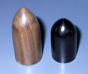
I don't know how to design phase plugs yet, but working on it. Of the ones I have shaped so far, the shorter ones appear to be better, so I need to try even shorter ones.
I am using the classic bullet shape. I think in the "design", too many factors come into it, ie the shape and angle of the apex, and the rate of curve if curvilinear. I want to devise a better way of shaping too. Did the first lot on a grinding wheel, then sandpaper.
I do know that I will shape dowel before fitting tweeters and/or eq. Somehow they bring out a lot of clarity and spread the beam . No filter will do that.
Geoff
I don't think so. We are talking about improvements, not methods.
I don't know how to design phase plugs yet, but working on it. Of the ones I have shaped so far, the shorter ones appear to be better, so I need to try even shorter ones.
I am using the classic bullet shape. I think in the "design", too many factors come into it, ie the shape and angle of the apex, and the rate of curve if curvilinear. I want to devise a better way of shaping too. Did the first lot on a grinding wheel, then sandpaper.
I do know that I will shape dowel before fitting tweeters and/or eq. Somehow they bring out a lot of clarity and spread the beam . No filter will do that.
Geoff
Attachments
- Status
- Not open for further replies.
- Home
- Loudspeakers
- Full Range
- Visaton B200 - Taming the shout