Hi all,
So in the end you went with the Silhouette Few. Did you decide it wouldn't be possible or practical to get the etching process to work well? I noticed earlier in the thread you widened the gap in the layout from .5 mm to something around .75mm? Anyone have any luck etching traces on the order of .5mm? I'm thinking about a small tweeter a la the Neo3's. It seems like in the case the narrower one can make the traces the better to pack more into the space the better.
Dan
Hi Dan,
I've been audio-incapacitated by my work schedule in recent months so I've not had anything worth reporting. I have a new computer, which meant freshly reloaded software for the Silhouette but, to my relief, it looks like that worked.
From my fewer than 10 attempts I found I could semi-reliably use the etching approach at the 0.75 mm gap level. I was using long patterns, at the limit of the screen I used to transfer the pattern. Most of the limitations I encountered were near the ends of the pattern so you might be able to push the resolution limits a bit if you aim for a shorter pattern. The approach still has merit but I found the reliability wasn't there for the dimensions and technique I used. You may very well find it's great for a shorter conductor pattern.
Few
Hi Few,
Yes, it sounds like it would be worth experimenting with for me then. Were you able to resolve the issue you had a few pages back with the the etchant getting under the pain and etching the back side of the aluminum? If so, did it just require a thicker application of adhesive or more cleaning of the aluminum foil surface?
On the Silhouette, do you know what the resolution of the cuts it can make is? I haven't been able to find this info so far. Would it be able to cut traces as small os .5 mm?
thanks,
Dan
Dan,
The Silhouette has quite fine resolution, as Solhaga's image shows. The trick is keeping the aluminum stable (not peeled off the substrate and not torn) during the cutting. That can get trickier as the traces become very narrow.
I found with the etching that getting a perfect silk screen is important. The blocked regions have to be truly uniformly blocked and the clear regions have to be completely clear. It took me a few tries to understand how picky you have to be at the mask-making step.
With a good mask the remaining trick is getting a perfect paint layer. With very fine traces or gaps any slight motion of the mask relative to the aluminum while the paint is going down will cause trouble. You have to force paint through a fine mesh, a process which requires a bit of force, so keeping everything properly registered requires a bit of practice.
I got worried that my yield (number of perfect traces divided by the number of attempts) with the etching approach was going to be frustrating so I decided to try the Silhouette approach. I think the switch was the right move for me but it's still tricky to find the perfect match of materials and cuttings parameters. I hope to get back to that process in the next few days.
Few
I finally got a few minutes of breathing time so I could return to the cut aluminum method of fabricating planar magnetic diaphragms. The aluminum-paper laminate that Bernt provided is clearly much easier to work with than anything else I've tried. Thanks again, Bernt!
To improve my technique without wasting too much material I've been making lots of test cuts of small patterns. Along the way I got interested in planar magnetic headphones as an interesting application but getting sufficiently high impedance in a headphone-sized diaphragm requires narrow, and narrowly spaced, traces.
To that end, I tried pushing the gaps between traditional serpentine conductors narrower and narrower. As my blade dulled it became difficult to avoid tearing the foil when the traces and gaps were sub-millimeter. Yesterday my new ebay-sourced blades arrived so I've started playing again with narrow conductors. In fact I pushed into a different realm.
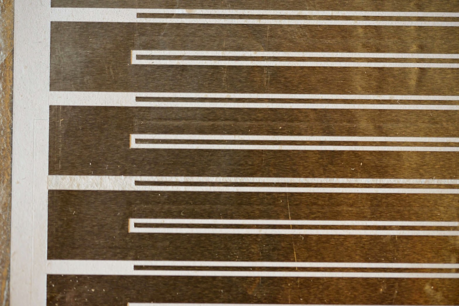
Up until now I had been making traditional serpentine patterns as shown earlier in this (now old!) thread. The Silhouette makes such consistent cuts, though, that I thought I might get away without leaving waste between conductive traces---waste that then has to be carefully removed. Instead, I decided to just use a single slice to separate parallel traces, and not design in any removable waste.
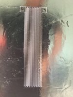
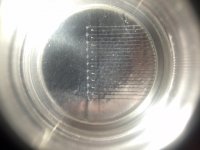
The attached photos show a quick test of the idea. The first shows light shining through the slices in the aluminum foil. The second was taken through a measuring magnifier. Both are just iphone photos so the quality isn't great but I'm hoping they're clear enough to convey the results. The measuring magnifier image includes a millimeter scale showing that the traces are 0.75 mm wide. (You have to look very closely to see the black scale lines.)
The main part of the pattern fits into a 17 mm x 70 mm rectangle and with 10 micron thick foil it has a resistance of 5.7 ohms. A headphone-sized diaphragm with acceptable resistance might actually be possible with this approach. I can fit 20 traces in the space that only held 6 with my original screen printed pattern. The slice method certainly minimizes the undriven diaphragm area!
The obvious question is how reliably the cut gaps stay as gaps rather than short out. So far it looks promising. I also have to determine how narrow a trace I can use for a speaker driver without sacrificing power handling and reliability.
Few
To improve my technique without wasting too much material I've been making lots of test cuts of small patterns. Along the way I got interested in planar magnetic headphones as an interesting application but getting sufficiently high impedance in a headphone-sized diaphragm requires narrow, and narrowly spaced, traces.
To that end, I tried pushing the gaps between traditional serpentine conductors narrower and narrower. As my blade dulled it became difficult to avoid tearing the foil when the traces and gaps were sub-millimeter. Yesterday my new ebay-sourced blades arrived so I've started playing again with narrow conductors. In fact I pushed into a different realm.
Up until now I had been making traditional serpentine patterns as shown earlier in this (now old!) thread. The Silhouette makes such consistent cuts, though, that I thought I might get away without leaving waste between conductive traces---waste that then has to be carefully removed. Instead, I decided to just use a single slice to separate parallel traces, and not design in any removable waste.
The attached photos show a quick test of the idea. The first shows light shining through the slices in the aluminum foil. The second was taken through a measuring magnifier. Both are just iphone photos so the quality isn't great but I'm hoping they're clear enough to convey the results. The measuring magnifier image includes a millimeter scale showing that the traces are 0.75 mm wide. (You have to look very closely to see the black scale lines.)
The main part of the pattern fits into a 17 mm x 70 mm rectangle and with 10 micron thick foil it has a resistance of 5.7 ohms. A headphone-sized diaphragm with acceptable resistance might actually be possible with this approach. I can fit 20 traces in the space that only held 6 with my original screen printed pattern. The slice method certainly minimizes the undriven diaphragm area!
The obvious question is how reliably the cut gaps stay as gaps rather than short out. So far it looks promising. I also have to determine how narrow a trace I can use for a speaker driver without sacrificing power handling and reliability.
Few
Attachments
nice results, such small traces get wam quick, i used 40 micron verry narow(1mm) once, and they got hot fast.
Thanks for the response WrineX. A couple of questions if you don't mind:
I'd like to be able to calculate what width of conductor I should use given the 10 micron thickness of the foil and overall driver dimensions but I don't yet have an equation or spreadsheet that lets me play with the relevant parameters. If anyone can point me toward such an equation please do so!
- You said 40 micron (1 mm). What are the two dimensions?
- Also, were you running the driver as a single tweeter, or single mid/tweeter? I ask because I'm planning on building a linear array that's 1.5 - 2 meters tall so each driver won't need to sink as much power for a given SPL.
I'd like to be able to calculate what width of conductor I should use given the 10 micron thickness of the foil and overall driver dimensions but I don't yet have an equation or spreadsheet that lets me play with the relevant parameters. If anyone can point me toward such an equation please do so!
40 micron thick foil 1mm wide track (40 micron = 0.040 mm). i used it as mid/tweeter that worked pretty well. but cross exteme low 300< they will get hot 🙂 i think the foil you got from bernt is even 10 micron thick ?
but you can easily use wider tracks if you are gone build a 2 meter tall one. or you end up with a resistance of 20 ohm or more 🙂 and lose eficieecy to. or you make 2 of them with the small tracks and put them in paralel. or wide tracks and put them in series. there are allot of posibilities.
usually ur magnets dictate what you can do trackwise. leaving allot of unused mylar is never a good idea , the tweeters sound the best when as much as the foil is used to drive the menbrame.
else it gets boomy and the highs are not that sparkle you are looking for
Last edited:
Thanks for the clarification regarding the trace dimensions.
I do intend to use a combination of series and parallel connections of the linear array of drivers. Until I know what the final impedance of a single driver is I won't know which combination will get me to the 4 - 8 ohm range but that's where I intend to end up.
I'm planning to cover as much of the diaphragm with useful conductor traces as possible. My NdFeB magnets are 0.25 inches wide and I'm still fiddling with FEMM to figure out the best magnet spacing. I'd like to use a single-ended system rather than push-pull but I'll need to have working prototypes before making a final decision.
Thanks again for the input.
push pull did raise mine with 6dB almost, and it sounded better to. but it is indeed allot harder to build. i used verry low power cheap rubber magnet , with neo's its eve dangerous to make a push pull. first hard to put together and if it even flips you dont want your hand in between the plates.
- Status
- Not open for further replies.
- Home
- Loudspeakers
- Planars & Exotics
- Viability test: DIY screen printing for planar magnetics