If two red LEDs have too high a Vf then try replacing one or both with IR LED. 1.75Vf+1.3Vf=3.05V
Or replace one with a signal diode.
1.75Vf +0.75Vf = 2.5V
Between Schottky diodes, signal diodes, IR LEDs, red LEDs, yellow LEDs and green LEDs, you have an enormous range of compound possibilities from ~1V to ~4V in small increments.
Do you agree that getting this voltage drop correct is the source of my DC offset problem? I have lots of diodes and LED combos to use.
I don't know this amp. I do know when I was working on the inverted version of the other amp that currents and voltage drops across the non symetrical stages, that small errors gave very disproportionate voltage errors.
http://www.diyaudio.com/forums/soli...uestions-answers-post4078500.html#post4078500
and post109 give some clue on set up difficulties.
http://www.diyaudio.com/forums/soli...uestions-answers-post4078500.html#post4078500
and post109 give some clue on set up difficulties.
Last edited:
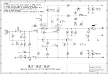
Schematic
XRK,
I explained a detail post and then lost the !@#$ text.......
1. Voltage across Vbe multiplier, Q4, from C to E of BD139. Should be 1.90 volts
2. Voltage across LED and series 4004 diodes. Should be 3.25 volts
3. Voltage from gate of Q6 nmos to base of inverter, Q5. Should be 5.19 volts.
4. Voltage across R20, for 0.47R this should be around 50mV
5. Voltage at output wrt ground, should be 0mV but I think it's about +2? (positive?)
6. Voltage wrt ground at left side of VR1, should be -3.2V.
7. Voltage wrt ground at right side of VR1, should be -3.82V.
8. Voltage at wiper of VR1, and voltage at base of Q1, all wrt ground.
1. XRK: remeasured at 1.196v for 103mA bias current
As I rotated the BD139 back in place after measuring, the B pin touched a protrusion connected to +35v rail. The Blue LED died. I went back and replaced the blue LED and it lights up but the amp pegs the rail and draws 17v across the 10R safety resistor. Without the safety resistor, the IRFP got very hot quick - I could smell stuff coming off I assume either the IRFP240 is dead and shorted, or something is driving its gate wide open. Although the IRFP240 doesn't measure 0ohms across pins - still in the ten kohm to Mohm range when installed Something else died.
2. voltage across 2 red LEDs is 3.50v
XRK: remeasured at 3.49v across red LEDs
HD: This gives us a total bias voltage of 2.13+ 3.50= 5.63. This is a heavy bias; you could increase the resistance in the BASE to EMITTER of the Vbe multiplier so that the voltage across the entire shebang reduces to Thimios' value, that is 5.19V rather than 5.63V. This should reduce the idle current around 100mA, and if it's 400mA it should be then 300mA, but to be honest this is a bit too high. I would not use more than 150mA. Even then it will be pretty warm, this is 0.15 x 70 = 10.5W, about what it should have.
XRK: I reset to 23mV for 0.22R
3. nmos G (-) tp Q5 base (+) is -5.06v
Now, you have replaced the blue LED and hopefully the BD139 as well. Double check you have the BD139 correctly fitted; collector to TOP of bias generator, to gate of the nmos via the gate stopper; and the emitter to the ANODE of the blue led then down through a 1N4004 anode, then cathode of this diode to the base of the phase inverter. You have 5.06V from top of BD139 to cathode of the 1N4004, and this should be correct.
The kathod of the 1N4004 goes to the emitter of the Voltage Amplifier Stage (the KSA1381), and the collector of this transistor passes to negative rail.
Check all you connections against the schematic from Thimios/Prasi. You have a major issue here and you have to find the problem, this needs discipline.
Now, the ensure C7, the bias generator 47uF electro, straddles the Collector of the Q4 BD139 right down to the cathode of your !N4004 - it should now have 5.06V right across it.
Now, the offset. Let us from the output of the amp, back. This is a technique of electronics; you assume the amp is operating correct, and then count back to find the significant voltages.
Let's assume the output offset is ZERO, 0mV, as intended. Most of the current, some 98% of it, will pass through R9, the 1K resistor. The current through this resistor will be determined by the voltage across Q2 base/emitter, since this 1K resistor, R7, will always have 0.62V across it, so it is in fact 0.62mA. When this current comes through Q1, the 2N5401/A992, and will therefore be the same and also come through R9, 1K. Again, 0.62V across R9, add the 0.62V across emitter/base of Q1, and we finishing up with around 1.24V at the base of Q1. But the base current through Q1 will be around 0.62mA collector current/Hfe, which will be around 7uA, or 0.62/100 x 1000 to convert into uA. This base current will come through R5, which I assume is now 33K, and when you multiply this 7uA x 33k = 231mV, that is, 0.231V. This voltage now adds to the -1.24V we have wrt ground at the base, and the total voltage needed at the wiper of VR1 will need be -1.471V.
Now it all becomes clear to me. You should delete the TWO REDLEDs, and put in two 1N4001s (or 1N4148) in place of BOTH of them. You will then have close to -1.4V at the left side of VR1. A 200, or even 100R trimmer here is fine and with this 200R trimmer you should be within 10mV, pos or neg after adjustment.
This should have it going nicely.......
Get to this point, and then measure the voltages, and let me know and we can then polish it to get output offset less than a couple of mV.
Cheers,
Hugh
Last edited:
Hi Hugh,
Thanks for the very clear electronics lesson. I had wondered about6the effect of those two red LEDs when earlier I measured and mine were so much higher drop than you suggested. This may be the reason Thimios and I both ended up with 51k in R5. I'm going to try replacing them with diodes and putting31k back in R5 and test again. Are you still of the mind that R4 should be removed?
Thanks, Terry
My pleasure, Terry, thank you for reading it, understanding it, and appreciating it!
It is amazing that so much can be figured with Ohms Law and very simple maths. We really need only the DC conditions to get an amp to go; but the magic is in the AC currents and voltages, and that's where the CRO comes in.......
Cheers,
Hugh
It is amazing that so much can be figured with Ohms Law and very simple maths. We really need only the DC conditions to get an amp to go; but the magic is in the AC currents and voltages, and that's where the CRO comes in.......
Cheers,
Hugh
I explained a detail post and then lost the !@#$ text.......
That used to happen to me a lot. I discovered that I was hitting Ctrl A instead of Shift A which was highlighting the entire text and the next letter typed would erase everything. My son pointed out that if I would then hit Ctrl Z it would all come back. Thought I would share this tip while I was thinking about it. 😀
Now, you have replaced the blue LED and hopefully the BD139 as well. Double check you have the BD139 correctly fitted; collector to TOP of bias generator, to gate of the nmos via the gate stopper; and the emitter to the ANODE of the blue led then down through a 1N4004 anode, then cathode of this diode to the base of the phase inverter. You have 5.06V from top of BD139 to cathode of the 1N4004, and this should be correct.
Hi Hugh,
What schematic are you using? I don't see the 1N4004 diode on the schematic. I replaced the 3.3V zener with a blue LED. Are you saying that I should have replaced it with a blue LED in series with a 1N4004?
Thanks, Terry
Hi Hugh,
Thanks for the very clear electronics lesson. I had wondered about6the effect of those two red LEDs when earlier I measured and mine were so much higher drop than you suggested. This may be the reason Thimios and I both ended up with 51k in R5. I'm going to try replacing them with diodes and putting31k back in R5 and test again. Are you still of the mind that R4 should be removed?
Thanks, Terry
+1!!
Nothing like being taught by such a master in the field with a hands-on project

Thank you Hugh.
p.s., it is a truism that when things come easy, we don't learn as much as when things are more difficult to achieve. An amp that fires up first time with no issues would not have taught me the finer points as I am receiving here from Hugh and the other members. So, it's good to step back and remember the journey and the education I am getting from it. 🙂
Last edited:
Terry,
I am wrong; we should start with the Vbe multiplier (BD139+R+Trimpot) then the blue LED below and the C7 electro across collector right down to cathode of bled. APOLOGIES!
With total 5.2V and 2.6 at the bled we are left with 2.6V also across tne BD139. This is OK but i would like to see 2V only across the BD139 to reduce the thermal compensation to better match the nmos as it warms.
Andrew was correct; he twigged to the excessive led voltage; we really about -1.47V at the trimpot wiper to pull the offset down to 0mV.
XRK you catch on fast; thank you for learning so easily. Many learners are resentful and it slows it down!
HD
Last edited:
It was Xrk that twigged
I don't know this amplifier.
I just gave him many alternatives to obtaining lower voltage references.Aksa, when you say voltage drop across LEDs and 1N4004 should be 3.25v that means LEDs alone should be 3.25-0.56v or 2.70v. I am measuring 3.5 is across the 2 red LEDs.
I don't know this amplifier.
Terry,
I am wrong; we should start with the Vbe multiplier (BD139+R+Trimpot) then the blue LED below and the C7 electro across collector right down to cathode of bled. APOLOGIES!
Andrew was correct; he twigged to the excessive led voltage; we really about -1.47V at the trimpot wiper to pull the offset down to 0mV.
XRK you catch on fast; thank you for learning so easily. Many learners are resentful and it slows it down!
HD
So can we just use one red LED rather than two or are we better off with two 1N4148 in series?
No Terry you might be talking of the bias string supporting the base of Q1 and here twi 4148 diodes are fine. I was referring to the bias generator which sets the quiescent in the output stage!
Hugh
Hugh
Hi Hugh,
Yes I should have been more clear. I understand that we will just use the one blue LED for the VBE multiplier. I am referring to the two red LEDs at the offset trimmer. It seems you are saying that we want -1.47V where I have -3.6. I am I still misunderstanding?
Yes I should have been more clear. I understand that we will just use the one blue LED for the VBE multiplier. I am referring to the two red LEDs at the offset trimmer. It seems you are saying that we want -1.47V where I have -3.6. I am I still misunderstanding?
The blue LED at Vbe multiplier seems to do a good job of providing range of bias current adjustments.
I think my problem is caused by the two red LEDs at the DC offset part of the pre-input stage. That would be great if two 1n4148's will work. Perhaps a single red could work even. We already have a blue LED so no need for more lights. The blue is an annoying color though. It is so bright, it washes out my vision and cannot look at PCB without covering it up.
I think my problem is caused by the two red LEDs at the DC offset part of the pre-input stage. That would be great if two 1n4148's will work. Perhaps a single red could work even. We already have a blue LED so no need for more lights. The blue is an annoying color though. It is so bright, it washes out my vision and cannot look at PCB without covering it up.
Hi Eric.
It is great DIY in learning and it takes time what it needs- not a race- if you are to much in hurry- causes not recognized little adversities.
I hope that all 3 builder here can be successful assemble the little Gift.
My thought is only to bring a nice project a bit more run forward.
The last posts brings a lot electrical information- little lessons to learn- Thank you Hugh.
I follow.
Cheers Bangla
What should i say about rapidness?Hi Bangla H,
Just received my pair of boards, thank you very much !!
Don't expect my boards to be complete in a few days like XRK and Terry..lol..I'm a slow builder
It is great DIY in learning and it takes time what it needs- not a race- if you are to much in hurry- causes not recognized little adversities.
I hope that all 3 builder here can be successful assemble the little Gift.
My thought is only to bring a nice project a bit more run forward.
The last posts brings a lot electrical information- little lessons to learn- Thank you Hugh.
I follow.
Cheers Bangla
XRK,
It is 9am here - I am refreshed!
I would not replace two 4148s on the Q1 bias network because you need -1.47V and a single red led delivers 1.6V which is too high.
You can replace the blue led however with a green led (2V) and a 4148 in a row. This gives you 2+0.7=2.7V and offer a more congenial light.
HD
XRK,
It is 9am here - I am refreshed!
I would not replace two 4148s on the Q1 bias network because you need -1.47V and a single red led delivers 1.6V which is too high.
You can replace the blue led however with a green led (2V) and a 4148 in a row. This gives you 2+0.7=2.7V and offer a more congenial light.
HD
Hi Hugh,
How do we get to 1.47V? We have two red LEDs there right now.
Hi Hugh,
How do we get to 1.47V? We have two red LEDs there right now.
As I understand it, Hugh still wants is to replace both red LEDs with two 1n4148's and not some combination of LEDs or diodes.
For Vbe circuit replace blue LED with a green plus 1n4148 for a more subdued light. But if you are good with blue light I wouldn't change it.
- Home
- Amplifiers
- Solid State
- Very simple quasi complimentary MOSFET amplifier