XRK,
Yes you would need both channels to hear depth of image!
However you do have two channels now?
I just meant for recording mono sound clips, the spatiality would not come through. Only in stereo and probably only in person can that be experienced.
I used a MJE350 because I thought it needed low gain. I thought that is the reason you singled out the BF470. Would KSA1382 be better? I have plenty of those. Incidentally, I played it hard all day and it is rock solid. It held 100mA throughout all temperature ranges so I would say the thermal compensation is spot on. Offset is stable and only shows 40mV for a minute or so and then settles to zero. These latest values are good to go.
As for higher rails, one thing should be kept in mind. Q3 runs a good deal hotter when you get above 36V rails. At +-36V it is good without a heatsink.
As for higher rails, one thing should be kept in mind. Q3 runs a good deal hotter when you get above 36V rails. At +-36V it is good without a heatsink.
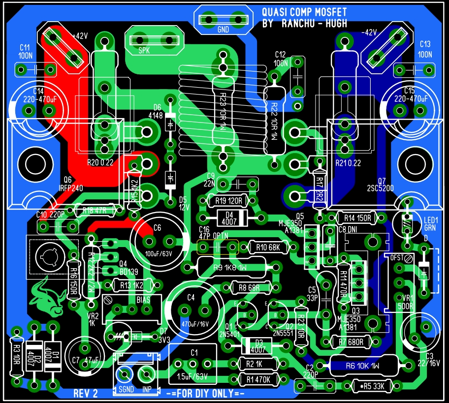
This amp with IRFP/C5200 output stage will work to 42V rails (30Vac supply) but not for 4R loads.
HD
Thanks Hugh for your reply. But as I already mentioned, I am interested in higher power at 4 ohm load, because my 2 way speakers are 4 ohm rated and I have a 30-0-30AC 300VA torroid ready.
If nothing else, I may eventually choose to use a Cap Multiplier and regulate the supply to 36V DC.
Any thoughts on doubling the Output Stage? Thanks.
Hi Samuel
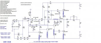
The weak link here is the 2SC5200. To drive 4 ohm speakers from 42V rails you really need to double-up that NPN, which may be easier said than done with this topology, since the lower half of the output stage forms a CFP, and these tend to be difficult to stabilise with two more more output transistors.
You may be lucky and be able to simply duplicate the 2SC5200 as well as its base stopper and emitter resistor, but I wouldn't recommend doing it unless you have access to an oscilloscope to test it out.
Hi Samuel
The weak link here is the 2SC5200. To drive 4 ohm speakers from 42V rails you really need to double-up that NPN, which may be easier said than done with this topology, since the lower half of the output stage forms a CFP, and these tend to be difficult to stabilise with two more more output transistors.
You may be lucky and be able to simply duplicate the 2SC5200 as well as its base stopper and emitter resistor, but I wouldn't recommend doing it unless you have access to an oscilloscope to test it out.
Or use a NJW3281 or MJL4281 as they present better SOA.
Marc
Or use a NJW3281 or MJL4281 as they present better SOA.
Marc
Hi Marc I was about to ask same thing 🙂. Also the biggest of them all Sanken 2SC2922?
Good idea 🙂
At -/+35vdc or -/+50vdc njw and mjl have same soa so better use njw as they have smaller package and lower price .
Marc
Thank you everyone for your inputs. I would try Cap Multiplier/Regulated Supply for a start with 2SC5200 before moving on to upgrades.
At -/+35vdc or -/+50vdc njw and mjl have same soa so better use njw as they have smaller package and lower price .
Marc
The MJL4281 with its bigger package will do a better job of dissipating all that heat, which is confirmed when comparing the datasheets. It also has slightly less droop at higher currents. We are talking about a 4 ohm load with fairly high rail voltages - so every bit counts.
Personally, I would double-up the outputs but if we are limited to just one then I would not hesitate to choose Onsemi's premium part, the MJL4281. In fact I have on many occasions with excellent results 😉
I reckon a single 2SC5200 will fail with that load, and if its a fake then it will likely fail sooner rather than later.
Yep, agree with Christian.
Samuel, I would move to a tougher mosfet AND bipolar, OR, try a tougher mosfet and two C5200s, matched. But I caution you that this is a different amp; you are asking for more power into 4R, and necessarily you need a different output stage. I did a mosfet/bipolar complementary amp some years back, the NAKSA 100, and I used a FQA40N15 Fairchild (40A, 280W, 150V) and a matched pair of C5200 (genuines). Then of course you are obliged to drive the npn pair with a heavier duty phase inverter; in that situation I would advice a CFP bipolar 2N5401/BD139 to replace the existing single transistor BF470/KSA1381 used on the existing schematic.
With that output stage you can easily drive 4R speakers and even lower, and it is much simpler than a regulating power supply, which I do not recommend for its complexity, cost, and affect on headroom.
Ciao,
Hugh
Here is TPC with nested NFB around VAS and total GNFB is 30 dB only.
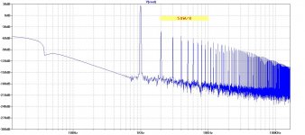
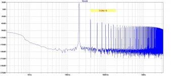
Distortion is higher of course, but dominated by second harmonic and the same throughout whole audio band.
I used better model for IRFP240, found here in Cordell-models. (quasi saturation region, par. ksubthres).
Damir
Distortion is higher of course, but dominated by second harmonic and the same throughout whole audio band.
I used better model for IRFP240, found here in Cordell-models. (quasi saturation region, par. ksubthres).
Damir
Attachments
Hi Damir,
Thank you for the results! Are you able to calculate the loop gain at 20k?
These THD figures are higher than most full global, complementary designs, but not too bad, less than 0.05% in simulation is acceptable (no doubt higher in reality), but I suspect that the loop gain does not drop around 3-5KHz like a full global feedback amp. In my view this has some relevance to the subjective perception across the entire audio spectrum because the loss of loop gain does not change much during the audio spectrum. The BC560C is limited to Vce 45V according to the datasheet; not recommended for this supply but otherwise very good models.
Thank you also for the calculations of TMC compensation, Damir, the ULGB at 2.87Mhz AND phase margin is very high for an audio amplifier.
Ciao,
Hugh
Last edited:
Hi Damir,
Thank you for the results! Are you able to calculate the loop gain at 20k?
These THD figures are higher than most full global, complementary designs, but not too bad, less than 0.05% in simulation is acceptable (no doubt higher in reality), but I suspect that the loop gain does not drop around 3-5KHz like a full global feedback amp. In my view this has some relevance to the subjective perception across the entire audio spectrum because the loss of loop gain does not change much during the audio spectrum. The BC560C is limited to Vce 45V according to the datasheet; not recommended for this supply but otherwise very good models.
Thank you also for the calculations of TMC compensation, Damir, the ULGB at 2.87Mhz AND phase margin is very high for an audio amplifier.
Ciao,
Hugh
Hugh,
Here are the Loop Gain plot and FFT plots for 1kHz and 20kHz at 50W/8.
The Loop Gain is flat up to 100 kHz.
I have built amplifiers with ULGF close to 4 MHz (200W CFA and 100W) and my CFA with triple BJT OPS (Unique) was built, with no stability problems whatsoever.
cheers,
Damir
Attachments
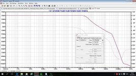
Thank you Damir!! I had never realised the loop gain continued so far - mind you that's TMC, but it is good...
Your amps measure very well and I recall talking with you about your brilliant voltage stage - it was original and innovative.
Hugh
Your amps measure very well and I recall talking with you about your brilliant voltage stage - it was original and innovative.
Hugh
Thank you Damir!! I had never realised the loop gain continued so far - mind you that's TMC, but it is good...
Your amps measure very well and I recall talking with you about your brilliant voltage stage - it was original and innovative.
Hugh
Hi Hugh,
This is TPC, I've found that it's better suited for CFA, and TMC for VFA.
By the way, nothing innovative in my designs, I picked here and there different configuration, except probably how I combined compensation, TPC with Miller cap from the output to the FB input (Cherry). That compensation I used in 200W CFA, 100W CFA and Unique CFA too.
Damir
Last edited:
Why THD20k /1W is slightly higher than THD20k/ 50W? The circuit need higher bias?Here is TPC with nested NFB around VAS and total GNFB is 30 dB only.
Distortion is higher of course, but dominated by second harmonic and the same throughout whole audio band.
I used better model for IRFP240, found here in Cordell-models. (quasi saturation region, par. ksubthres).
Damir
- Home
- Amplifiers
- Solid State
- Very simple quasi complimentary MOSFET amplifier