So here's a gerber for ordering the boards. If anything, Pete will help you figure it out (because he was able to figure it out with the previous version).dont forget this is still a hobby....
Attachments

but I never want to say that you are wrong. of course there is logic in your words and I understand it.
No worries...you are entitled, as the designer, to state your opinion on what you think gives the best result for your creation. You did give us the option for different op amps and no “set” component build schema.
For instance, I didn’t like the overall sound (on my speakers, in my living room with my old R&R declined hearing 😉 using AD825 so switched to NE5534 opamps and the sound is more pleasingly clean. Plenty of bass & lower end (for those who started this sub-forum please name a few recordings to judge mid-bass inadequacies with). On one set of speakers I get a slight "thump" when I turn off the power but yet on another set (with a more complicated x-over network) there is no "thump” so a speaker protection relay circuit might be a good option to consider.
I agree with Chris as I am not learned enough to design one of these amps myself and I am grateful to folk for giving us these projects to build and evaluate. Yup, I will say I’m a hobbyist too. I’m not ashamed of the moniker. 😉
I think someone who wanted a compact build using the 7293 would find this amp does a nice job and offers up a bit of fun building it. I wouldn’t recommend it for a newer hobbyist who needs handholding throughout the process though.
Pete
Last edited:
but I never want to say that you are wrong. of course there is logic in your words and I understand it.
So here's a gerber for ordering the boards. If anything, Pete will help you figure it out (because he was able to figure it out with the previous version).
That’s the gerbers for post #34? What’s your thoughts on the re-design compared to the original? A quick glance looks like another set of caps in front of the opamp (which is also an SMD mount now?)
I think I sense sarcasm 🙄 ...excellent! I wish Chrome did a better job of translating your Russian page to English cause I’m sure some electrical build concepts just didn’t come across clearly.
Pete
Firstly, I started to draw a circuit and noticed an error in the gerbera. There is missing one resistor to ground from the negative input of the op amp. I'll redo it and post it later. good news - drew a circuit. I'll come home from work, I'll post it. Pete felt sarcasm and yes, he was there just a little, but not even sarcasm, but self-irony, since in reality the article is not very good. I tried to embrace the immensity, in short. it was necessary to divide it into two and dwell in more detail on the parts of the amplifier circuit and draw it in more detail. I just had a remnant in my head, I thought it was simple, I thought that everything was just as simple for the others ... but in vain. I think to remake and rewrite the article on another resource, stop in more detail on some details that are not clear to many. Now that the amplifier has been repeated by as many as five people, I already understand what questions may arise.
Last edited:
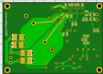
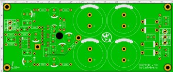
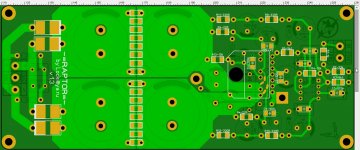
So, gerber corrected in the archive. The difference from the version that Pete made is that everything is redone on the SMD and the CRC chain is added, additionally filtering the power supply of the operational amplifier. Well, the scheme and screenshots are attached.
PS ^ the words, that seemed ironic to Pete, meant only, that I don't come here often, I can not answer at the right time. And Pete already understood my thoughts in this scheme, as he made a similar one.
PS ^ the words, that seemed ironic to Pete, meant only, that I don't come here often, I can not answer at the right time. And Pete already understood my thoughts in this scheme, as he made a similar one.
Attachments
-
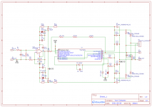 Schematic_TDA7293SMD_2021-04-09.png100.9 KB · Views: 183
 -
Schematic_TDA7293SMD_2021-04-09.pdf72.5 KB · Views: 176
-
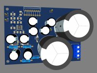 tda7293_3D_t.jpg109.5 KB · Views: 181
 -
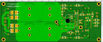
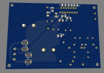 tda7293_3D_b.jpg93.1 KB · Views: 173
 -
tda7293.zip34 KB · Views: 103
-
 TDA7293_S.jpg271.1 KB · Views: 123
 -
 TDA7293_b.jpg139.8 KB · Views: 171
 -
 TDA7293_t.jpg229.4 KB · Views: 179
Last edited:
the protection is built into the 7293 chip, it seems, but I use an additional one from Aliexpress on optocouplers (to exclude the ground loop)
the protection is built into the 7293 chip, it seems, but I use an additional one from Aliexpress on optocouplers (to exclude the ground loop)
Astaro: much appreciation towards the new PCB layout. I’m not sure which protection circuit you are addressing here?
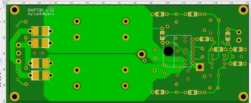
Is it possible to move the 6.8R SMD to the underside of the board with the rest of them?
Thanks,
Pete
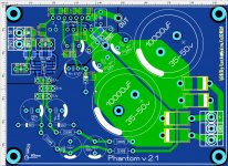
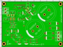
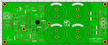
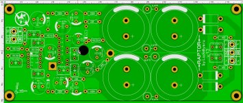
And who will say what about this option? The board is positioned parallel to the radiator. The high-end edition: more capacitors in the power supply, "blackjack and fallen women" and other things (like snubber in the power supply). I will could also power it separately by pre-filtering the legs of the pre-stage (legs 7 and 8)
Attachments
Last edited:
Someone is ready to collect for himself and write here as a sound and with what he compared. if there are any, I can post a link to order boards
I finished it. If there are those who want to repeat and unsubscribe, I am ready to give gerber for ordering boards.
Astaro: the tda7293 is in the middle of the board. How are you going to attach it to a heat sink or am I looking at this incorrectly?
Pete
I just did not do the"H" version, but under the usual one, just she needs to bend her legs 90 degrees so that she lies on the radiator, and her legs go into the board, lying parallel to the radiator, too.
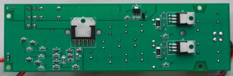
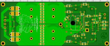
Now it's like this
Everything is filtered by CRC. It can only be cleaner with a stable power supply.
It remains to write a very good detailed article
Everything is filtered by CRC. It can only be cleaner with a stable power supply.
It remains to write a very good detailed article
Attachments
Last edited:

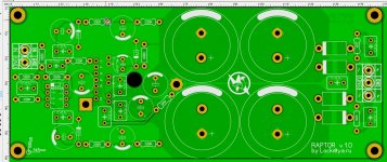
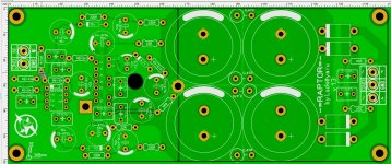
I think this is the final version.
I don't know what else can be improved here...
I don't know what else can be improved here...
Attachments
Last edited:
Hi Astaro
if i compare the input with post #33 i see that you omit the input cap(2,2µ//10nF)
Why?
chris
if i compare the input with post #33 i see that you omit the input cap(2,2µ//10nF)
Why?
chris
- Home
- Amplifiers
- Chip Amps
- Very low MID-bass in TDA7293