yes yes, i seeThe TLO72 is a great opamp... don't believe all you read about it. Trust what you hear.


its the key 😎
im uploading a video but my internet connection bores me 🙁(
and here is the 50hz brum 😀
https://www.youtube.com/watch?v=00aOzM8w9jI
and some fun -> https://media.giphy.com/media/ZX2mGcdth0FMc/giphy.gif 😀

https://www.youtube.com/watch?v=00aOzM8w9jI
and some fun -> https://media.giphy.com/media/ZX2mGcdth0FMc/giphy.gif 😀
this does not apply to a lateral fetsThe issue is the problem of "thermal runaway." When the MOSFETs get hot, the bias current increases, and this increase in current causes the MOSFETs to get even hotter, which causes the bias current to increase even more, and so on until the entire system overheats and fails.
this does not apply to a lateral fets
I readed in jilny's thread but they are too expensive. These are 1$, others 7-8$..
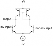
Hey this long-tailed pair is very interesting but they are many many questions and different combinations..
I think i will use two npn's with one resistor as load and current mirror as bias of both.
Maybe i need another transistor between the output stage and the pair ?
10pf compensation ?
Another question: look at the attachement, i readed this is an improvement but why then its not used in audio circuits ?
I do not want to use many transistors, so I need only 1 current mirror..
Attachments
Last edited:
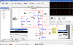
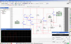
Attaching circuit that i have found and tweaked to minimize dist.
This was before my fail tries and this was the first fail. The problem wass too high bias voltage 🙂
However I never tested it and this is a big distortion 😀 0.034
I have soldered this as "module" part and need test.
However i dont want to use this circuit, i have seen better ones like in jilny's thread. ( I dont understand much but common sense 🙂 )
Attachments
New modification: added switch between two modes: party mode and night mode. THis mess up with the feedback, paralleles a resistor to the other one because when too sensitive there is a loud brum and the quality is better in night mode..
I calculated that its better to use 4.7k for gate stoppers because freq with 4.7 and 670p (input gate capacitane) is 50khz instead 1Mhz !
I think this stops more oscillations.
You will cee when I make an amplifier with two same fets, long tailed pair (full range output voltage), single supply, and 0% distort !!!! 😀
P.S. And yes what about ANALOG Full bridge :OO this may be MADNESS 😀
Imagine +- 70V output voltage :OO
Imagine some paralelled fets and a 700W real power 😀
Imagine that 10A @ the peak 😀
Nice.
P.S. 2. I have many many not working ATX supplys and What about 1kW SMPS delivering 700W to the amplifier 😀
with long tailed pair <3
My common sense make me love this LT pair, i do not know why 😀
Ahh i have many PSUs without big heatsinks for the AMP :OO
Maybe some day 😀
For now power class D would suit.
Attachments
Last edited:
another question: how many watts approx. is this transformer ?
And a problem: 50hz brum. Is this from power supply capacitors ?
They are 4700uf aand I short circuited them many times unexpectedly.. They are damaged or they are too small ?
Heyy, nobody answered me these questions 😛
Transformer are rated in VA (volt-amps) and so you need to know the secondary voltage and its rated current.
4700uF caps cover most filtering requirements, If you have 50 Hz hum then the problem is likely to be elsewhere. Shorting them occasionally shouldn't harm them as such.
4700uF caps cover most filtering requirements, If you have 50 Hz hum then the problem is likely to be elsewhere. Shorting them occasionally shouldn't harm them as such.
Transformer are rated in VA (volt-amps) and so you need to know the secondary voltage and its rated current.
4700uF caps cover most filtering requirements, If you have 50 Hz hum then the problem is likely to be elsewhere. Shorting them occasionally shouldn't harm them as such.
There is no info for the transformer, it is from my cousin's not working woofer, fully free 🙄
Amp sounds very nice
 , only this hum is very bad bad 😡@@
 Listen it to it very much
I designed a long tailed pair and it gonna blow 😀
CLEAR SOUND, FANTASTIC
I think i must get this bigger heatsink from the woofer 😀
I thinked repairing the woofer but maybe later later, some years 😀
At normal listening doesnt heat, but for party, heats a lot gonna blow 😀
Last edited:
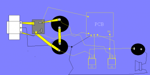
Regarding your hum problem: please draw just a brief layout in paint which shows
your components (PS, input, amplifier, Speaker, etc...) and ALL GND wires first.
your components (PS, input, amplifier, Speaker, etc...) and ALL GND wires first.
Thanks! And how is the input connected?
Where the signal GND is going?
BTW: how the hum changes when the input is shorted or open?
Where the signal GND is going?
BTW: how the hum changes when the input is shorted or open?
I dont see the zeners, where they are?
So the input GND goes only to the PCB?
And what about the hum with shorted and with open input?
So the input GND goes only to the PCB?
And what about the hum with shorted and with open input?
tommorow will test, my mum and dad are sleeping and this hum awakes them 😀I dont see the zeners, where they are?
So the input GND goes only to the PCB?
And what about the hum with shorted and with open input?
zeners are here look @ the attachement.
from the board (zeners) there is another wire to the common ground
Attachments
Hehe, ok! 🙂
So in total how many GND wires are going to/from the PCB to main GND?
And on your video the hum changes. What caused this difference?
Also you could take a close picture from your PCB from the top.
So in total how many GND wires are going to/from the PCB to main GND?
And on your video the hum changes. What caused this difference?
Also you could take a close picture from your PCB from the top.
Hehe, ok! 🙂
So in total how many GND wires are going to/from the PCB to main GND?
one wire from signal to PCB and one wire from PCB(zeners and the fb) to main GROUND.
And on your video the hum changes. What caused this difference?
I was touching the cable with finger ? 😱
Also you could take a close picture from your PCB from the top.
Also tommorow. Dont have time now.
P.s. Oh loook at the first video link, there is a close lookup of the board and its good quality, so..
Last edited:
Ok, I don't see any major trouble with your ground wires.
But it's still not clear: when do you have this hum?
Regarding yout video: which wire did you touch when it increased?
And what happaned at 0:17 when the hum completely disappeared?
But it's still not clear: when do you have this hum?
Regarding yout video: which wire did you touch when it increased?
And what happaned at 0:17 when the hum completely disappeared?
- Status
- Not open for further replies.
- Home
- Amplifiers
- Solid State
- very good mosfet design failure