Hi Rich,
As you see in the circuit diagram, this zener is AC-shunted with 47µF, which is more than plenty (I would have used a single digit µF value) to short circuit any noise to gnd.
But I would have used 4x 30V Zeners or something in series instead, since those high voltage Zeners generally have a very bad temperature dependend behaviour (which means they drift in value while they heat up).
Voltage regulator tubes both have advantages and disadvantages. You can´t predict at which voltage they "fire" exactly (a few single volts up or down their nominal value) but they show much less voltage drift once "fired". And they produce less noise than Zeners, that is right.
Anyway, a few volts more or less, or a few micro-Volts of noise more or less, is nothing to worry about in such an app. I would turn my eye on reliability issues instead.
Tom
richwalters said:Interesting design......That 120V zener in the g2 supply: In a sim circuit I worked on I found them very noisy which was breaking into ajacent wiring. Perhaps I had another type but I was forced to use tube stabiliser.
Anyone using H.V zeners in circuits .. Which makes can be recommended ?
As you see in the circuit diagram, this zener is AC-shunted with 47µF, which is more than plenty (I would have used a single digit µF value) to short circuit any noise to gnd.
But I would have used 4x 30V Zeners or something in series instead, since those high voltage Zeners generally have a very bad temperature dependend behaviour (which means they drift in value while they heat up).
Voltage regulator tubes both have advantages and disadvantages. You can´t predict at which voltage they "fire" exactly (a few single volts up or down their nominal value) but they show much less voltage drift once "fired". And they produce less noise than Zeners, that is right.
Anyway, a few volts more or less, or a few micro-Volts of noise more or less, is nothing to worry about in such an app. I would turn my eye on reliability issues instead.
Tom
Tubes4e4 said:But I would have used 4x 30V Zeners or something in series instead, since those high voltage Zeners generally have a very bad temperature dependend behaviour (which means they drift in value while they heat up).
It’s actually 2x62v, most because it was hard to find 120v zeners. Noise, I can’t hear any and I can’t see any on my scope. 47uF is more than enough, but I had one side of one the 2x47u cans left, and I used that one to decouple the 120v. The 120v is not very critical, but higher voltage will give the tube more "drive".
A tube stabiliser had of course been more fancy for the eye. 😉
richwalters said:The EF184 was another veteran which was popular in 1950's TV if stages and some audio amp manufacturers used this tube in pairs
as a long tailed phasesplitter. Although the transfer graphs are remarkably "straight", one ought to recon that low distortion was on the cards....it needs a fair amount of currect....but many amps using this tube sounded "lifeless"........only my point of view that longtail phasesplitters sound worse than other configurations.
richj
Say what!
 I finally completed a project that uses an LTP for phase splitting purposes (6SL7 + cascoded BJT CCS in the tail) and I don't think it sounds lifeless. What, exactly, does that mean anyway? So far, scoping the LTP output shows excellent balance from about 5HZ to 40KHz. Indeed, this is the first time I ever saw anyone criticize using an LTP for phase splitting.
I never had any luck in getting low thd from a longtailed pair and amps using this required high B+ and alot of nfb to get it down. The phasesplitter as it stands usually hulls around 5% thd at 50+50v rms drive when fed into 50K load and when loaded into output stage it rises even more. It isn't a load bearing performance.
What is the best mu tube that gives credible performance with this configuration ?
richj
What is the best mu tube that gives credible performance with this configuration ?
richj
But I would have used 4x 30V Zeners or something in series instead, since those high voltage Zeners generally have a very bad temperature dependend behaviour (which means they drift in value while they heat up).
what i do in this case is i mount these diodes as close together as possible on the pcb and then coat them with silicon grease so they thermally track each other.😀
richwalters said:I never had any luck in getting low thd from a longtailed pair and amps using this required high B+ and alot of nfb to get it down. The phasesplitter as it stands usually hulls around 5% thd at 50+50v rms drive when fed into 50K load and when loaded into output stage it rises even more. It isn't a load bearing performance.
What is the best mu tube that gives credible performance with this configuration ?
richj
OK, I see your problem here. What I did was to use the 6SL7 for a LTP splitter. These use 220K plate resistors (gives THD= 0.37% (est)) and drive 6SN7 cathode followers which drive the finals. In this case, the LTP isn't "load bearing", as that's left to the followers. Not really sure what the THD is since any harmonics dissappear into the noise when I used a T notch filter to reject the fundamental.
Cathodynes also get good reviews, with the caviate that the unequal impedances might cause unbalance at the higher frequencies. Basically, that's why I went with the LTP.
I use 5751's in LTP driving 6CG7's in SRPP to drive push - pull 300B's. The whole amp is under 1% at 10 Watts. The driver board frequency response (at the 300B grids) was flat to 50 KHz. There is no feedback anywhere in the amp. No CCS either, the cathodes are returned to the -200 volt supply through a resistor.
Hi Tony,
I tried a stack of zeners and ended up with the same positive temperature coefficient as the single 100V zener. 5W was a little better than 1W. The ambient temperature had a large effect too. So mount them in the coolest spot you can find.
Mine were used as the reference in a regulator, so I was able to use negative temperature coefficient resistors to compensate else where.
Do not use thermal grease, encourage as much cooling air flow as possible.
-Chris
hi chris,
thanks for the tips..... i do operate my zener stack at a fraction of its rating so it does not really heat up that much.😀
thanks for the tips..... i do operate my zener stack at a fraction of its rating so it does not really heat up that much.😀
May seem long-winded but one gets ideal breakdown performance. One of my favourite ones is to string loads of 5V1 zeners to the desired voltage and then epoxy the lot.. Has near zero temp drift at optimum 5V1 with brill temp cooef. A single h.v diode in soft avalanche breakdown has a dreadful spec.
richj
richj
Hi,
Here are some measurements from my Sweep AMP.
6LU8 in PP.
B+: 320V
NFB: 14dB
Power: 2x12W rms (conserative rating), 2x25W peak
Damping: >6x (1kHz) (Zuot <1.3R)
Band wide: 18-40kH (-1dB@1W),
S/N: >70dB
THD <0.5% 12W (-52dB 3ndHD@400Hz@12W)
And some curves that shows the Vertical deflection amp in action:
Distortion: 12w Output 400Hz input: (-52dB 3dr@12W)
3kH square wave (1Vrms@3kH)
Here are some measurements from my Sweep AMP.
6LU8 in PP.
B+: 320V
NFB: 14dB
Power: 2x12W rms (conserative rating), 2x25W peak
Damping: >6x (1kHz) (Zuot <1.3R)
Band wide: 18-40kH (-1dB@1W),
S/N: >70dB
THD <0.5% 12W (-52dB 3ndHD@400Hz@12W)
And some curves that shows the Vertical deflection amp in action:
Distortion: 12w Output 400Hz input: (-52dB 3dr@12W)
An externally hosted image should be here but it was not working when we last tested it.
3kH square wave (1Vrms@3kH)
An externally hosted image should be here but it was not working when we last tested it.
Miles Prower said:
Cathodynes also get good reviews, with the caviate that the unequal impedances might cause unbalance at the higher frequencies.
Somewhat off-thread, but one needs to be careful here. It would appear that since one signal source is from a plate, the source impedance must be higher than the other from a cathode (follower). But if one looks at it from the viewpoint that the same current must flow through equal value resistors (they are in series in the equivalent diagram), this unbalance does not exist as long as the 2 impedances remain the same, i.e. as long as the external loading on the plate remains the same as on the cathode.
That's exactly right- with equal impedances, the balance is essentially perfect. The trouble happens when you drive a stage that is not class A1; when you cut off one tube or conversely drive one tube into grid current, the load symmetry is broken. And the asymmetry changes from side to side in an unequal manner. This is one of the beauties of the Williamson circuit- the output stge is buffered from the split load inverter.
J.C Morrison sums up cathodynes simply; if one uses med mu voltage amp as an interface to output stage which uses common cathode for balancing, the performance is excellent and I always use this technique. The inherent impedance snags of the cathodyne disappear.
To keep parasitic capacitances to a min I always use triode config pentodes. Ex TV video tubes are xcellent performers and there are alot around.
If one uses an 7199 followed by such stage, workout the stage gains...with a med/highish mu tube as the interstage can be too high then one comes up against the amp signal/noise ratio versus input voltage.
richj
Hello,try the 6MF8 same pinout you don't need 120V G2.jane said:Has anyone played around with vertical deflection tubes (6LU8, 6LR8, 6KY8, triode with power pentode) for audio purposes?
A pair of 6LU8 looks promising in a small push pull setup: you'll get 2 high mu triodes, one for input stage and one for phase splitter (split load) and two beam pentodes with Pa of 14w each. Looks like a better candidate in terms of power than in example ECL86 and friends.
But I cant find much information on the net using those kind of tube for audio -- any obvious pitfalls using them?
Cheers!
Looked at some of those myself, only quite expensive end cost for us here in SA.
Only be careful, Sing Santa,
Data is given at different G2 voltages, but maximum values are the same for 6LU8 and 6MF8 (at least in my RCA Tube Manual, 1970.) Only 6LU8 power half is more sensitive than
6MF8.
Only be careful, Sing Santa,
Data is given at different G2 voltages, but maximum values are the same for 6LU8 and 6MF8 (at least in my RCA Tube Manual, 1970.) Only 6LU8 power half is more sensitive than
6MF8.
Hello everyone,
i just want to tell ,i build up a PP Amp using 4 times a PL36.
These tubes are very cheap deflection tubes (4Euro) and give 175Watt RMS at 420 volt plate and 200volt screen.
I build this for a subwoofer in my house.The plans are from a guy in england,who converts amps from EL503 to PL/EL36.
The Raa is 1K2 and the Bias current is about 35mA.
This amp is sounding very well also in full range usage.So using deflection tubes is a good idea for amps which are not following the main stream for tubeamps.(and still sound amaising)
grz Burkhard
Madmoony said:So using deflection tubes is a good idea for amps which are not following the main stream for tubeamps.(and still sound amaising)
grz Burkhard
Definitely so. I did a project with 6BQ6GTBs, though these are horizontal deflection types, not vertical. They do sound awesome.
But I would have used 4x 30V Zeners or something in series instead, since those high voltage Zeners generally have a very bad temperature dependend behaviour (which means they drift in value while they heat up).
It is because so called "zener" diodes above ca 6V are in reality avalanche diodes with a comparable high positiv tempco. You can partly compensate that positiv tempco by serial connecting some real zener diodes (voltages below ca5V) that have a negative temp coefficient
Last edited:
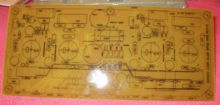
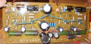
The 6LU8 can go 160V on the screen. I prefer 380V B+ and fixed adjustable bias tuned to about 35mA. I use a damper diode for slow start from a diode rec to a large cap, only the first cap recommended 500V takes the brunt of the diodes. I only had a couple 400V caps for use after the slow start, 450V caps are on order. I found a 12lb organ PT on fleebay for $25 with HV taps for 300 and 380V, Im using the 300 for the B+. It also has 5.3Vac and 13Vac taps so I'm running the 6CG3 on 5.3Vac and put the 6LU8's in series off of the 13Vac. The pics shown was a set up on a Hammond PT with 8Amp 6.3Vac tap, the Hammond was borrowed from another project to bring life to this PCB.
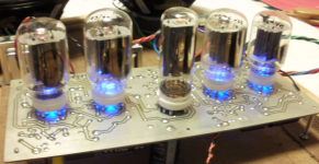
I tried 8K-8 20 watt iron, OK and then used 6.6kRaa Bogen iron with just a little feedback. Quiet as a church mouse, and can drive 89db speakers with ease. Not all 6LU8 tubes are made the same, I've had a few "tested" not last long during their audition when I received them.
This amp was a spin off of a 6JT8 PP amp that I was designing as a headphone amp using little merit universal transformers. I've been making 12AU7-Mosfet hybrid headphone amps and wanted to try something different, but that is another post....
Attachments
Last edited:
- Home
- Amplifiers
- Tubes / Valves
- Vertical deflection tubes for audio output?