sir jay,
pinkmouse said
it's got a horrible ground layout, I'd avoid.
http://www.diyaudio.com/forums/solid-state/198630-limiter-connections.html
but i was expecting words from apex too.
pinkmouse said
it's got a horrible ground layout, I'd avoid.
http://www.diyaudio.com/forums/solid-state/198630-limiter-connections.html
but i was expecting words from apex too.
apex protect,zeck
Attachments

Last edited:
hello mile can you pls help me how to know if the limiter circuit is working any procedure how to test it?
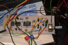
vertex with limiter
Thanx mile
limiter connected to vertex amp
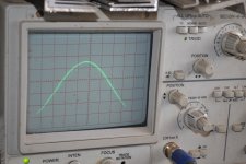
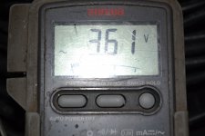
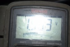
3.6v rms on limiter input at 50hz and limiter output is 1.5v rms at 50hz
Thanx mile
limiter connected to vertex amp
3.6v rms on limiter input at 50hz and limiter output is 1.5v rms at 50hz
Attachments

Hello Sir Alex,
I'm interested to make this amplifier as my next project. Will you be able to post the final and working pcb for this amplifier here? I'm sure many of us here (DIYers) will make this one. Thank you so much in advance.
Blueice23 🙂
I'm interested to make this amplifier as my next project. Will you be able to post the final and working pcb for this amplifier here? I'm sure many of us here (DIYers) will make this one. Thank you so much in advance.
Blueice23 🙂
sir jay,
please spare 2 pcs of mjl5851/52 for me,
i found it too difficult to buy high voltage pnp driver in RAON,
email sent😀
please spare 2 pcs of mjl5851/52 for me,
i found it too difficult to buy high voltage pnp driver in RAON,
email sent😀
blue ice,Hello Sir Alex,
I'm interested to make this amplifier as my next project. Will you be able to post the final and working pcb for this amplifier here? I'm sure many of us here (DIYers) will make this one. Thank you so much in advance.
Blueice23 🙂
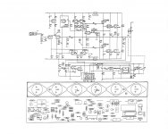
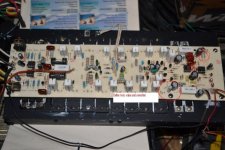
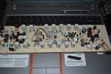
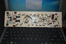
amp is already working,limiter also working
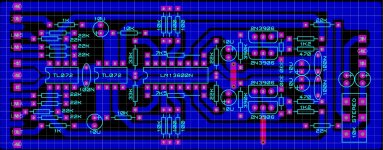
picture on page 1 post#1 is working unit
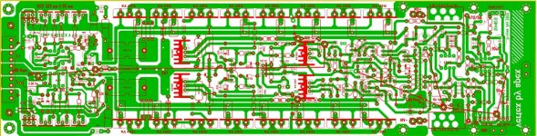
page 1 post #7 the green 1 is updated pcb
if anyone want to help upgrade pcb is much welcome since driver transistor need to be mounted on main heatsink,we are in need of pcb expert like sir COOLET.
but amp is working and stable with measurement already post and with speaker load test by sir jay
Attachments
with the right power supply
and with genuine output trannies
this amp can achieve power close to
1200w@8R
2200W@4R
4400w@8R bridged
6600w@4R bridged
can you imagine how much power this amp can give
and with genuine output trannies
this amp can achieve power close to
1200w@8R
2200W@4R
4400w@8R bridged
6600w@4R bridged
can you imagine how much power this amp can give
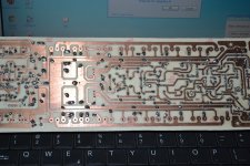
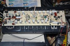
Very nice work 🙂 Before you powerup make absolutely sure there are no miniscule contacts by copper left-overs from the etching, there are some bulges on corners that are pretty close to neighbouring traces. It may be hard to see visibly.. Just talking from experience, you wouldn't be the first to be caught by lurking short circuits between traces.
LOL thanx for reminding me MagicBox and i know what im doing its my second board prototype of vertex and I've done and test several amp not just this one,i also use magnifier,electronics microscope to make sure all traces are not shroted
😛
😛
file's already been posted pls read the whole thread .
that second board is not the final one its same as the first board
file that been posted is updated
that second board is not the final one its same as the first board
file that been posted is updated
Last edited:
- Home
- Amplifiers
- Solid State
- Vertex Amp By apexaudio