Thank you very much. Using test points results, I calculated 16.5ma.About 15ma.
Hi John Curl-- I want to know your opinion!?
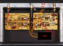
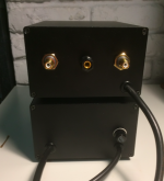
Advise the circuit XLR . to get the Balanced XLR output and immediately after your corrector send a signal to the XLR balanced amplifier. Thank. Sergey Moscow
how to make it simple and beautiful?
Advise the circuit XLR . to get the Balanced XLR output and immediately after your corrector send a signal to the XLR balanced amplifier. Thank. Sergey Moscow
how to make it simple and beautiful?
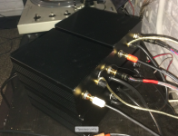
Attachments
Last edited:
HI
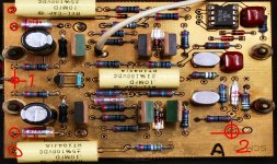
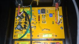
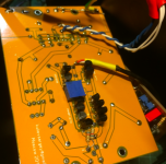
I collected --- there is a problem
I used Chinese parts-- ordinary
transistors are soldered to the bottom of the board
I connect a tube amplifier ----- the sound is heard only if the volume control is in a certain position If you unscrew the sound to the maximum there is no sound and to the minimum
Sound is only in a certain position on the amplifier
If you connect to the TV there is sound --- but somehow quietly
there is always a sound, it is regulated
Can someone tell me valuable advice
47k ---- need to install?
200 ohm +47 k ----- put this together?
my head denon 103
Attachments
Last edited:
the sound is heard only if the volume control is in a certain position If you unscrew the sound to the maximum
there is no sound and to the minimum Sound is only in a certain position on the amplifier
The volume control may be connected wrong, check the wiring.
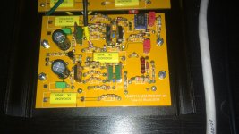
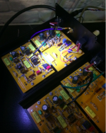
ok! The problem was in the chip!(I removed ne5534 put ad 711)
It works great!
I removed the input tuning resistor 200 ohms! I put a 1k resistor at the input
my head Denon 103
It works great!
I removed the input tuning resistor 200 ohms! I put a 1k resistor at the input
my head Denon 103
Attachments
Last edited:
PCB Prototype & PCB Fabrication Manufacturer - JLCPCB
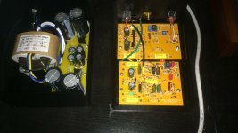
I drew on a computer - ordered at the factory here
I drew on a computer - ordered at the factory here
Attachments
Last edited:
You should not use a 5534 for the servo.
I believe John used the AD 711 back then ( today maybe OPA 189, or 134 )
carbon film resistors are not good either, at least use metal fim , preferably non magnetic ones .
I believe John used the AD 711 back then ( today maybe OPA 189, or 134 )
carbon film resistors are not good either, at least use metal fim , preferably non magnetic ones .
You should not use a 5534 for the servo.
I believe John used the AD 711 back then ( today maybe OPA 189, or 134 )
carbon film resistors are not good either, at least use metal fim , preferably non magnetic ones .
thanks for the advice
You should not use a 5534 for the servo.
I believe John used the AD 711 back then ( today maybe OPA 189, or 134 )
carbon film resistors are not good either, at least use metal fim , preferably non magnetic ones .
Because diferent input bias current between AD711 and 5534
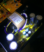
Also for yellow capacitors.
Use polypropylene (or polystryrene) MIT/ Relcap
Rel cap is John Curl’s choice.
( teflon Relcap too, but very expensive)
1% for the yellow cap in the middle (RIAA)
Use polypropylene (or polystryrene) MIT/ Relcap
Rel cap is John Curl’s choice.
( teflon Relcap too, but very expensive)
1% for the yellow cap in the middle (RIAA)
Hi, where could you source the J203 FETs from? You can replace them with current sources I guess, but maybe they can be sourced cheaper from somewhere. Thanks!
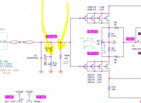
For purpose to learn more about how to get this circuit working with available jefts, I did this simulation with very good results.
Input Jfets: Idss = 16.3mA
Power Supply: 6 parallel Jfets per rail ( plus 1 Jfet for current source )
C1 and R15 values were modified for better FFT presentation.
C134 and C135 used for my own tests. They don´t belong to original topology.
Input Jfets Idss of 16.3, is it for one device? What is the total value of parallel Idss for K170/J74 pairs at the output of MC stage in your schematic? Regulated voltage ( 19-20V) seems high for servo op-amp which is 18V rated.
Last edited:
- Home
- Source & Line
- Analog Line Level
- Vendetta Research SCP-2A