The DC offset at the output is handled by the DC servo, the opamp, but you need to start with matched JFETs at the input, and matched FET at the output are a nice touch, to minimized DC offset. Remove the servo when measuring for raw DC offset.
Good Luck.
Good Luck.
You measure DC offset at the output, without the servo. Not sure about the differences where you are showing whether they need to match, probably should be minimize distortion products.
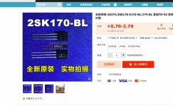
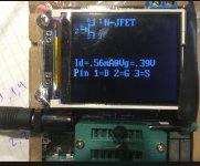
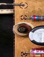
Where did you buy K170/J74? Looking at the top of the TO-92 package in your preamp I am sure they are fake. There are not original Toshibas with short line at the side of the top. Measure Vgs using Erno Borbely measuring jig. It should be 0.3 to 0.6V.
bought in china - nowhere else
he. writes the original - probably a hoax
see attach. 2sk170
he. writes the original - probably a hoax
see attach. 2sk170
Attachments

Last edited:
signal input - 1 kHz signal - 1 mV(computer)
12 mV output !!!!?????(vendeta)
Is this normal for MC head ? or is it a small gain?
I do not have a real head to check MC
12 mV output !!!!?????(vendeta)
Is this normal for MC head ? or is it a small gain?
I do not have a real head to check MC
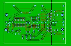
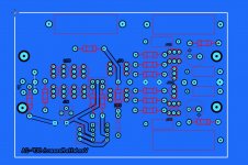
I took made a layout of this circuit (attach) - I burned the amplifier! High direct current output - why? Then slowly falls
Attachments
Last edited:
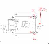
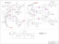
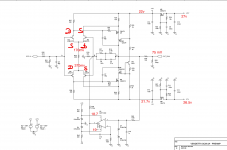
Looking at Federico Paoletti' schematic , first stage, you can change the value that resistor parallel capacitor in the rails to get 20V. Be sure that combined Idss from parallel jfets voltage supply is much more than the current used by each rail on first stage.
that's exactly what I did . but it remains a constant current, it's probably bad Chinese radio components and a microcircuit
Attachments

Last edited:
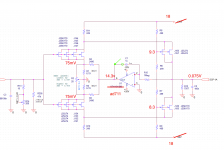
More recent simulations with MODIFICATIONS
For purpose to learn more about how to get this circuit working with available jefts, I did this simulation with very good results.
Input Jfets: Idss = 16.3mA
Power Supply: 6 parallel Jfets per rail ( plus 1 Jfet for current source )
C1 and R15 values were modified for better FFT presentation.
C134 and C135 used for my own tests. They don´t belong to original topology.
Attachments
Last edited:
Thank you try this option.!
The second part does not change? In your?
Yes, changes.
** The servo circuit has changed some values for simulation only. Other parts of circuit has values changed for correct results after modifications such as JFETs, Mosfet, etc.
Attachments
Last edited:

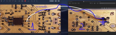
Are original Vendetta PCB holes plated with copper? There are ground pads on both sides but soldered only on one side.Is there connection to other?
I think so too ! - solder grounding on one side!
Attachments
Last edited:
- Home
- Source & Line
- Analog Line Level
- Vendetta Research SCP-2A