I agree very much with you rabstg.
By the way, i have also many other projects in progress, thats not the problem.
By the way, i have also many other projects in progress, thats not the problem.
Nordic said:Hi I am looking for the schematic for this amp and PSU if I could have them....
The schematic is here:
http://www.diyaudio.com/forums/showthread.php?postid=748312#post748312
It should be a really simple project. The only problem is that this version incorporates three power supplies. You could do by using the same rail for the tube and the ICs, but at higher voltage, the tube will perform better.
Believe it or not. But this thing actually works!
I used 2*12V 120VA (+/- 17,5VDC) for LM3875
6V 5VA (6.3VDC) for filament and 555 timer
2*19V plenty VA (+/-51VDC) for tube anode-cathode supply
I got 2mV and 40mV DC offsets.
I used my spare Amperex test 6dj8 tube. I’ll try the Philips ECC88 later.
no audible hum on my 4 ohm test speakers. Of course I cannot say anything yet about sound quality because I am not yet trying this thing on my main speakers, since the power supply still isn't in a proper case yet... (Conrad has free shipping now... let's order some more aluminium 🙂 )
Also, I just used a standard serial cable, I have to replace the high current wires with some thicker ones.
I did not make more changes than the ones posted in this thread. READ THIS ENTIRE THREAT when building this amp.
If I remembed correctly by head the following changes must be made:
# proper diode direction in LM3875 supply. All eight diodes should be mounted the same direction, use common sense what a proper bridge rectifier should look like.
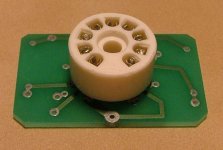
# mount the tube socket on the other side of the PCB to reverse pinout.
# replace the resistors by the 555 timer R5+R6=470K, so 47uf/25v for c17 gives enough time to stabilize. I did not time this, but I think it is something like 20 seconds.
# turn the 555 180 degrees
Also, follow the directions from Franz in the other threat about proper connection of the D-subs for the relay to work.
Before inserting the tube, just fire the thing up. You could leave out the LM3875 power supply first and check all the proper voltages on the tube socket.
This should be something like this (assume +/- 50V tube supply)
1 +50
2 0
3 -50
4 0
5 6,3
6 +50
7 0
8 -50
9 0
All values in volts with respect to GND.
If this is all correct and all ground wires are checked for proper connection it should be safe to plug in the tube (turn all power off first of course! 😉) , connect the LM3875 supply and hook up some test equipment.
Many thanks to Digi and Franz!
I used 2*12V 120VA (+/- 17,5VDC) for LM3875
6V 5VA (6.3VDC) for filament and 555 timer
2*19V plenty VA (+/-51VDC) for tube anode-cathode supply
I got 2mV and 40mV DC offsets.
I used my spare Amperex test 6dj8 tube. I’ll try the Philips ECC88 later.
no audible hum on my 4 ohm test speakers. Of course I cannot say anything yet about sound quality because I am not yet trying this thing on my main speakers, since the power supply still isn't in a proper case yet... (Conrad has free shipping now... let's order some more aluminium 🙂 )
Also, I just used a standard serial cable, I have to replace the high current wires with some thicker ones.
I did not make more changes than the ones posted in this thread. READ THIS ENTIRE THREAT when building this amp.
If I remembed correctly by head the following changes must be made:
# proper diode direction in LM3875 supply. All eight diodes should be mounted the same direction, use common sense what a proper bridge rectifier should look like.
# mount the tube socket on the other side of the PCB to reverse pinout.
# replace the resistors by the 555 timer R5+R6=470K, so 47uf/25v for c17 gives enough time to stabilize. I did not time this, but I think it is something like 20 seconds.
# turn the 555 180 degrees
Also, follow the directions from Franz in the other threat about proper connection of the D-subs for the relay to work.
Before inserting the tube, just fire the thing up. You could leave out the LM3875 power supply first and check all the proper voltages on the tube socket.
This should be something like this (assume +/- 50V tube supply)
1 +50
2 0
3 -50
4 0
5 6,3
6 +50
7 0
8 -50
9 0
All values in volts with respect to GND.
If this is all correct and all ground wires are checked for proper connection it should be safe to plug in the tube (turn all power off first of course! 😉) , connect the LM3875 supply and hook up some test equipment.
Many thanks to Digi and Franz!
Good news Hanzwillem. I myself received a bunch of parts from Conrad today. Still need to order some caps and than find some time to build the darn thing. 
Let us know how it sounds when connected to your proper speakers.
Regards
Let us know how it sounds when connected to your proper speakers.
Regards
Believe it or not. But this thing actually works!
Good news!
And many thanks to list all needed workarounds.
Again, I really regret all this problems. I learned, never to offer group buys before assembling and testing the final boards.
Happy ears!
Franz
congratulations Hanzwillem !! Nice to hear it works properly.
Two questions. In posting 59 is spoken about a resistor to make unther the board. Did you do that too as modification?
Is your trafo 2X12V 120V per LM3875? or do yopu use 1 such trafo for 2 chips? I think 1 such trafo has to low VA rate for 2 chips. Why you choose such low voltage? Normally i use 2x22V trafos for the LM3875.
Thanks for answering and like to hear your further impressions of the amp.
Thanks for the support guys!
The resistor under the board is the one Zang also mentioned. With a 47u capacitor and 470k resistor you will get enough time to stabilize before the relay will switch. The 470k resistor will go under the board as shown before. This one will replace the trimmer and the 100k resistor. Just look at the photo from Zang somewhere in the beginning of the thread. Of course you can still use the trimmer if you want to tune the startup time.
I use a 2*12V 120VA trafo because I had this one laying around. Mind that this one can deliver 5 amps per winding, that is the same as a 240VA 2*24V, so do not look at the VA rating alone. From my experience I know that higher voltages perform better. I have in my other gainclone two 2*22V 160VA trafo's but these have a low capacitance supply. I believe the influence is less with high capacitance supplies as used in this valve buffered amp. But I'll replace the trafo later with these bigger babies... probably when I get the new case for the supply next week.
With my 92dB sensitivy Focal speakers this trafo is plenty for now. I do not need more than 10W. I sit approx. 2 meters away from my speakers in a 14m^2 small room. It is all in the first watt... 🙂
Listening to the 3" test speakers this amp has big potential! 🙂
Moloko's pleasure seaker sounds real nice.
Thanks again for everyones help.
You are right GeWa!! C20 is in the PSU of the tubes AND in the PSU of the heater.
Maybey Hanzwillem knows it, his amp works.
Maybey Hanzwillem knows it, his amp works.

GeWa said:Zang, Franz
What kind of cap (type/value) do we use for C20 in the heater section?
This one is not mentioned in the partslist
C20 in the BOM refers to the one in the HT supply.
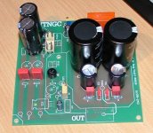
In the attached picture you can see that I'm slowly getting there.
it is a option cap,mine is wima 1uf/63v.
Hanzwillem,congratulations!
P.S.
I really regret all this problems.I will write a corrigenda soon.
Zang
digi01 said:
it is a option cap,mine is wima 1uf/63v.
Hanzwillem,congratulations!
P.S.
I really regret all this problems.I will write a corrigenda soon.
Zang
Thank you, Zang!
This little amp is a christmass present to myself 🙂
I do recommend everyone that has the PCBs laying at home to build this amp. It is playing on my main set; Peter Daniels premium DAC and Focal Cobalt 815 speakers for a few hours and already is the sound very good! Only a little bit hum, but on the 92dB speakers not really a problem. I do know that I like it already a lot better than my gainclone.
I am pretty sure the sound will improve even more over the next days, as the tube is NOS as well as the paper in oil coupling caps.
Kuddos to Franz and Zang!
Best wishes,
Hans-Willem
(btw, relay I used in the end was part nr: 504267 from Conrad)
I am pretty sure the sound will improve even more over the next days, as the tube is NOS as well as the paper in oil coupling caps.
Kuddos to Franz and Zang!
Best wishes,
Hans-Willem
(btw, relay I used in the end was part nr: 504267 from Conrad)
Hanzwillem
Did you have problems with the heater voltage? With a 6V trafo and an LM317 it's a bit of a tight margin to operate. 6V x 1,414=8,48V Those LM's need a 3V difference between in- and output. This is just a question of general interest, no comment. Just want to make sure it works before I connect everything. (still missing a tube though)
Cheers
Good remark! I did not even take that minimal Voltage drop into consideration. If I remember correctly by head I could get the heater up to 7.2V. That may be because I have 7VAC out of the trafo. Maybe I should replace the 317 with some low drop substitute, I think I have some laying around...
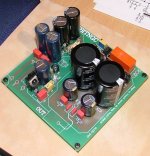
This is were I am so far. Substituted the LM317 voltage regulator with an LT1085 (low drop) to be on the safe side. Al the caps in the HT section are 100V types. I will be using a 22+22V trafo so 63V caps don't have any save margin in my setup. Still need the 33K and 220K resistors to finish it.
Hanzwillem
Which coupling cap (1µF) did u used? I have some Angela MKP 630V types that I want to try. (small size)
Cheers
Hanzwillem
Which coupling cap (1µF) did u used? I have some Angela MKP 630V types that I want to try. (small size)
Cheers
Attachments
I am pretty sure the sound will improve even more over the next days, as the tube is NOS as well as the paper in oil coupling caps.
Kuddos to Franz and Zang!
Many thanks! The first good news since some time 🙂
BTW: it is one year ago, I built the first version of the mini amp, as the whole story started with my last years christmas project.
Hanz-Willem: Your amp looks very smart and it is easy to change the tube. So, you could try different versions of the tube.
The amp should be hum free, with my 100dB speakers no problem.
How did you solve the ground wiring and the cabling between the psu and the amp?
Franz
ATM, I followed the grounding scheme posted by you in the other threat.
With exceptions in the following:
- I connected I tied the grounds of the rca's together and from there to the ground point on the amp. (I found the input holes way too small). Maybe I could make two separate wires to the star ground.
- the amp chassis is not yet grounded.
For the power cable I usa a serial cable for now. This week I am going to snatch some bigger wire at my university 🙂
This is my first project involving tubes, so I wanted to make sure I could look at that thing and see it glow. That is why I choose this look for the amp...
- Status
- Not open for further replies.
- Home
- Amplifiers
- Chip Amps
- VBITNGC building & comment