Hi Gareth,
The one place where you don't really want excess resistance is in the emitter circuit of a common emitter output stage. The other factor that is effective is the heat sink. If it's too small, you will have bias stability troubles.
Hi kees52,
I can see the smt glued to the collector lead as a very effective sense point. The thermal track mounted the sensing diode on the collector heat spreader internally. Sticking an smt to the collector lead is about as close as you're going to get outside the package.
Of course, that makes service a PITA! On the replacement part you'll have to glue another smt, without markings to know what it was. Hopefully it is used as a forward biased diode so that any one will do. Then, connecting the leads could be tense. Use kynar wire or single strands from wire? Either one is a total joy to work with. I can see the possibility of someone ripping the output out without seeing the smt, then you have the classic amp that no one can repair. Not unless you leave a note in the chassis.
-Chris
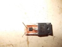
Hi Anatech, I have a irfp240 mosfet who has 0.18 ohm on resistance and not a bjt, because of this low resistance the current when cold rise very quick, the housing or the heatsink do not work very wel then, or I need use overcompensation, so as I have done now it is stable, even until the 90 degree temperature region what is very very hot.
I have gleu the bc817 smr onto the drain lead.
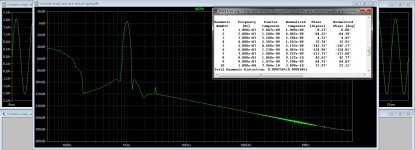
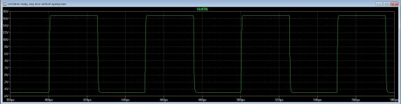
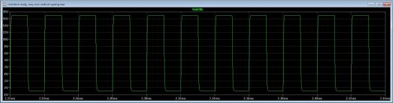
and in picture the distortion of the output of the circlotron allfet, now it is time to start pcb it, so I go back to mine own tread for that, I stay here for the multiplier afcourse, get new expericences I put that here..
regards
Attachments
Last edited:
@anatech
Yes the service is has some difficulties, however the sense transistor can also be set below the drain lead on the pcb, so it toch the power device.
What I had seen with opamps is even a better way, worth to look at it and sim. these days we have a lot of low voltage rail to rail opamps who can work nicely.
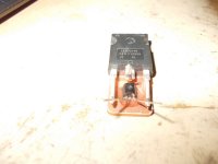
I have afourse to set into the case the warning when replace power devices one has a smt bc817 glued on it as a temp tracker, but maybe I have a better idea also, using copper, this is very good in temperature resistance, it is not for nothing it is much used in pc cpu coolers. the idea I did mention earlyer, this way replacing a power device is a easy task, I can use as sense transistor a sot223 transistor soldered on the copper sitting just below power transistor collector or drain lead.
regards
Yes the service is has some difficulties, however the sense transistor can also be set below the drain lead on the pcb, so it toch the power device.
What I had seen with opamps is even a better way, worth to look at it and sim. these days we have a lot of low voltage rail to rail opamps who can work nicely.
I have afourse to set into the case the warning when replace power devices one has a smt bc817 glued on it as a temp tracker, but maybe I have a better idea also, using copper, this is very good in temperature resistance, it is not for nothing it is much used in pc cpu coolers. the idea I did mention earlyer, this way replacing a power device is a easy task, I can use as sense transistor a sot223 transistor soldered on the copper sitting just below power transistor collector or drain lead.
regards
Hi kees52,
Your gate stopped resistors look to be a bit too low in value. You might want to watch for signs of ringing or oscillation in your outputs.
Your temperature sensor location is fine for what you are doing. Adding a piece of copper might not be the best idea. Keep it simple.
-Chris
Your gate stopped resistors look to be a bit too low in value. You might want to watch for signs of ringing or oscillation in your outputs.
Your temperature sensor location is fine for what you are doing. Adding a piece of copper might not be the best idea. Keep it simple.
-Chris
Hi kees52,
Your gate stopped resistors look to be a bit too low in value. You might want to watch for signs of ringing or oscillation in your outputs.
Your temperature sensor location is fine for what you are doing. Adding a piece of copper might not be the best idea. Keep it simple.
-Chris
The idea of copper was when blow a mosfet then replacement is quite easy, the copper is between the mosfet and the insolator, tracking heat very fast.
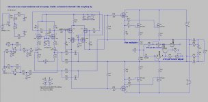
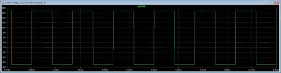
The gate stoppers are because the irfp240 has big gate capacity, the driver is in pure class a, I do afcause finetune the amp afterwards and the replece componentes for the right ones, this because simulation is not always precise,, like models are not always accurate..
pic's are 1 Khz 20Khz and 50Khz quite clear for a allfet amp who is prone for overshoot because these are capacitive devices but it is sim, need real world and go start with a pcb now winter is coming here.🙁
regards
Attachments
I guess SIMs can be useful, but I wouldn't trust the outcome as if that is the performance you'' get.
-Chris
-Chris
I guess SIMs can be useful, but I wouldn't trust the outcome as if that is the performance you'' get.
-Chris
Sims are most of the time very usefull to get a raw circuit, building it and trim is always needed, also because of pcb design and parasitics, who is very common in mosfets.
However the sim of the multiplier is quite accurate.
regards
Hi sam9,
All bipolar stages need thermal compensation of some sort unless they are not biased on. Whether they need a vbe multiplier or not is another question. Your thermal bar would be the heatsink in this case.
So depending on your circuit and thermal layout, you may or may not require the vbe multiplier (bias control circuit).
-Chris
On my designs I go for as low a bias current as is needed to get rid of crossover distortion. This usually results in just a few mA.
Some people like to use 100mA or more which is going to add to the heat in the heatsink.
Peavey also tend to go for low bias currents.
I always use a Vbe multiplier but just mount it on the pcb next to the heat sink rather than glue it to the heat sink.
When for guitar purposes it is not that critical, however for a high end amp it is important, for me a vertical mosfet needs much higher idle current to get it to low distortion and need a uge classe A driver also. a irfp240 with 0.15 ohm on resistance need a fast tracking, bjt is less demanding, the irfp needs 250 mA idle to get liniair, maybe even more, depending of driver capability to overide the nC of gate capacity.
I have a idea as in pic, using copper between mosfet and insolator get around the difficulty when service the amp as a mosfet do die.
regards
I have a idea as in pic, using copper between mosfet and insolator get around the difficulty when service the amp as a mosfet do die.
regards
Attachments
Last edited:
- Status
- Not open for further replies.
- Home
- Amplifiers
- Solid State
- Vbe Thermal Coupling Issue